Do you have a question about the Eco ETS 73 and is the answer not in the manual?
Identifies experts qualified to perform tasks described in the manual.
Specifies where to keep the mounting and operating instructions.
Provides contact details for distribution and after-sales service.
Lists available resources like brochures, training, and spare parts.
Defines the intended application for the swing door drive mechanism.
Explains symbols used to highlight residual dangers and facilitate work.
Outlines safety requirements based on standards like EN 16005/DIN 18650.
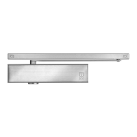
Introduces the ETS 73 swing door drive mechanism and its basic function.
Describes the normal motorized opening and closing of the door leaf.
Details the operation where the door opens via spring power during power failure.
Explains sequence control for bi-parting installations using CAN bus.
Specifies the location of the rating plate on the drive mechanism.
Lists detailed technical specifications like dimensions, weight, and power.
Defines usage limits without safety elements per standard EN 16005.
Provides graphical data for determining maximum wind-load capacity.
Steps and checks required before mounting the drive mechanism.
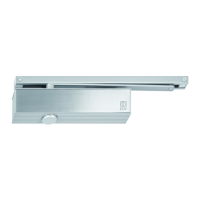
Presents different mounting configurations for rod assemblies.
Detailed mounting instructions for narrow rod assemblies.
Specific mounting steps for sliding rods in pulling function.
Specific mounting steps for sliding rods in pushing function.
Details for mounting rod assemblies made of stainless steel.
Detailed mounting for stainless steel normal rods in pushing function.
Detailed mounting for stainless steel sliding rods in pulling function.
Detailed mounting for stainless steel sliding rods in pushing function.
Detailed mounting for stainless steel sliding rods in leaf mounting.
Procedure for adjusting the closing spring tension for optimal operation.
Adjusting parameters for forceful closing to ensure door lock engagement.
Setting the activation point for the accelerating function.
Instructions and warnings for connecting the main power supply.
Recommendations for routing cables for lintel and leaf mounting.
Mounting and connecting external control and safety elements.
Overview and connection details for various types of motorized locks.
Connecting motorized locks directly to the motor coil.
Details for motorized locks with integrated or external evaluation control.
Information on motorized locks requiring a separate control and power pack.
Procedure for commissioning the drive mechanism in inverse application mode.
Configuring the opening and closing order for bi-parting door leaves.
Setting up interlock functions between two doors.
Instructions for applying service and diagram stickers.
Steps for installing the protective covering for the drive mechanism.
Describes the built-in main installation switch for power disconnection.
Explains how to enable operating modes using the program selector keys.
Details the functions of AUTOMATIC, NIGHT, OPEN, MANUAL, and EXIT modes.
Guide to adjusting operational parameters using the display and joystick.
Configuration of parameters like speed, hold-open time, and forces.
Setting various functionalities and relay outputs for the control unit.
Configuration for closing sequence and interlock in multi-leaf doors.
Explains how to navigate through the control unit's menu system.
Tools for checking system status, inputs, outputs, and error codes.
Information on active, historical errors and their display.
Procedures for re-initializing parameters and settings to default values.
Functions for joystick locking, unlocking, and the teach-in procedure.
A comprehensive checklist for annual service and maintenance.
Basic checks of components like cable connections and bearings during service.
Lists and explains malfunctions indicated by error numbers on the display.
Specific causes and solutions for drive mechanism related errors.
Solutions for errors related to operating modes and door movement.
Addresses issues with safety elements like SER, SES, and EMY.
Troubleshooting guide for power supply faults (30V, 24V, CAN).
Resolving general system errors and unexpected events.
Guidance for troubleshooting issues with optional PCBs.
Troubleshooting CAN bus and interlock function errors.
Identifies and resolves common issues not indicated by error numbers.
Steps for updating the control unit software using a USB stick.
Detailed steps for performing a software update via USB.
Interpreting LED indicators on the control PCB during the update process.
Common errors encountered during software update and their solutions.
Instructions for decommissioning and taking the installation out of service.
Information on environmentally responsible disposal and recycling.
Comprehensive list of available spare parts with article numbers.
Description of the D-BEDIX accessory for door control and programming.
Explanation of the functions of C, OK, and Arrow keys on the D-BEDIX.
Interpretation of symbols displayed on the D-BEDIX for operating modes.
Details the modes selectable via the D-BEDIX, including locking.
Describes how the D-BEDIX displays door status and errors.
Guide to accessing and navigating the D-BEDIX menu structure.
Practical examples for changing operating modes and keylock settings.
How errors are shown on the D-BEDIX display and where to find details.
Description of the KOMBI-D-BEDIX with integrated key-operated switch.
Information on an optional stop piece to prevent door leaf damage.
Details on the mounting plate for normal rod assemblies.
Information on standard and ETS 73 Mod mounting plates.
Instructions for optically connecting two drive mechanisms.
Introduction to optional PCBs that can be added to the control unit.
Details on addressing, commissioning, and enabling functions of the Relay PCB.
Procedure for programming the Radio PCB with transmitters.
Guidelines for mounting the LZR-FLATSCAN sensor on swing doors.
References to included wiring diagrams for various components.
| Brand | Eco |
|---|---|
| Model | ETS 73 |
| Category | Door Opening System |
| Language | English |