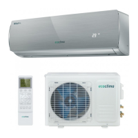
This document is a service manual for Ecoclima split system inverter air conditioners operating on 50Hz with R410A refrigerant. The specific models covered are EC(-W)/I-09QC(-B,-G,-W), EC(-W)/I-12QC(-B,-G,-W), EC(-W)/I-18QC(-B,-G,-W), and EC(-W)/I-24QC(-B,-G,-W).
Function Description
The Ecoclima split system air conditioner utilizes a PG indoor fan motor and a 4-pole brushless compressor with a rotary speed adjustable between 25-100rps. The outdoor controller incorporates an IPM transducer for compressor control and a PFC control circuit, achieving a power factor exceeding 95% for the complete unit. The primary control mechanism is based on the temperature difference between the indoor ambient temperature and the user-set temperature.
Operating Modes and Control Features:
- Capacity Control: Cooling and heating capacity are adjusted by varying the compressor's rotary speed. The transducer converts AC220V to DC voltage, and the IPM module controls the compressor's power supply.
- Indoor Fan Motor Control (PG motor): Offers multiple fan speeds: High, Medium, Low, and Gentle. In "Auto" mode, the fan speed is automatically selected based on room and set temperatures.
- Outdoor Fan Motor Control (AC machine): Provides High and Low fan speeds, determined by outdoor ambient and indoor pipe temperatures.
- Blades Control: Allows for tridimensional airflow. Vertical blades can swing automatically (1-5 point positions) or be set to a fixed position. The system stores the last blade position when powered off.
- Cooling/Dehumidification/Air Refresh: Blades swing circularly within the 1-4 range. Louver blades automatically adjust to prevent dripping.
- Heating: Blades swing circularly within the 2-5 range. During heating startup or defrosting, blades remain fixed to avoid blowing cold air until the evaporator temperature exceeds 32°C.
- "Smart" Function: Automatically judges the operation mode (cooling, heating, fan sweep) based on indoor, outdoor, and set temperatures. In "Smart" mode, all additional functions are available, indoor fan speed is automatic, louver swings automatically, and outdoor rotary speed is controlled according to the corresponding mode. Users can adjust louver position and temperature.
- Dehumidification: Operates in cooling mode if indoor temperature is higher than a certain value, or in dehumidifying mode with low outdoor fan speed. Compressor frequency is adjusted based on indoor temperature relative to upper and lower limits.
- Independent Air Refresh Function: Activates Fan Sweep mode when the unit is off.
- Timing On/Off: Allows scheduling of unit operation for once in 24 hours. Program timing control enables daily automatic on/off.
- Induction Function (Remote Controller): The remote controller sends room temperature signals to the air conditioner every 3 minutes. If no signal is received for 5 minutes, the unit operates based on the indoor temperature sensor.
Important Technical Specifications:
- Refrigerant: R410A
- Power Supply: 50Hz
- Compressor Frequency Range: 25-100Hz
- Rated Operating Conditions:
- Cooling: Indoor: 27°C DB/19°C WB; Outdoor: 35°C DB/24°C WB
- Heating: Indoor: 20°C; Outdoor: 7°C DB/6°C WB
- Tubing Length: 3m
- Max. Operating Value:
- Cooling: Indoor: 32°C DB/23°C WB; Outdoor: 52°C DB
- Heating: Indoor: 27°C; Outdoor: 24°C DB/18°C WB
- UVC Lamp: The appliance contains a UVC lamp for sterilization. UVC spectral irradiance can exceed 1.7 W/cm².
Usage Features:
- Emergency Run Button: Turns the unit off when in operation, or turns it on in Smart mode when off.
- Buzzer Sound: A buzz sound is emitted when any key is pressed during operation, or when "on/off", "air refresh", or "smart" buttons are pressed from off status.
- Power-Failure Automatic Reset: The unit automatically restarts to its previous settings after a power failure.
- Sleep Control (Soft Operation): Decreases compressor rotary speed and sets indoor fan motor to medium or low. Set temperature increases by 1°C after 1 hour, and again after another hour, but the displayed temperature remains unchanged.
- Dry Mildew Proofing Operation: The indoor fan motor continues running for a period after shutdown to dry residual moisture.
Maintenance Features:
- Over Current Protection: The outdoor controller monitors input current. If it exceeds a prescribed value, the compressor's rotary speed is reduced. If it exceeds the upper limit, the compressor stops.
- High-Loaded Prevention (Freeze-Prevention):
- Cooling: If indoor heat exchanger temperature is too low, compressor speed decreases to prevent freezing. If it exceeds the upper limit, the unit stops.
- Heating: Indoor heat exchanger temperature is monitored. If it exceeds a prescribed value, frequency doesn't increase. If it exceeds the upper limit, compressor speed gradually decreases to avoid high heat load. If it's below the lower limit, the unit enters high-loaded control and normal operation.
- Cooling Overload Working: If the outdoor heat exchanger temperature is too high during cooling, compressor speed is automatically adjusted to a lower gear, or the compressor may stop.
- Defrosting Control: Activated in heating mode based on the defrosting sensor (Te) detecting frost level. Defrosting conditions include running for specific durations and outdoor environmental temperatures. During defrosting, the outdoor fan stops. Defrosting ends when outdoor heat exchange reaches a prescribed value or after a set time.
- Blowing Surplus Energy Function: When the compressor turns off, the indoor fan motor operates at low speed (gentle/stop) to utilize residual energy from the indoor pipe coil.
- Temperature Control for Compressor Vent: A vent temperature sensor monitors refrigerant air temperature from the compressor to ensure efficient operation by controlling rotary speed.
- Timelag Protection for Compressor: A 3-minute delay is implemented before restarting the compressor after it stops or is initially started, except during defrost mode.
- Failure Indication:
- Outdoor Unit: Red light flashes for failures; green light indicates electricity.
- Indoor Unit: Error codes (F0-F9, FD, FE, E0, E3, E6-E9, P1, P3-P6) are displayed, often accompanied by specific red light flashes on the outdoor PCB.
- UVC Lamp Maintenance:
- Read maintenance instructions before opening the device.
- Unintended use or damage can cause dangerous UVC radiation, harmful to eyes and skin.
- Damaged appliances must not be operated.
- Disconnect power before cleaning, maintenance, or replacing UVC emitters/starters.
- Doors and access panels with UV hazard symbols have interlock switches to disconnect UVC lamp power for safety. Do not bypass.
- UVC barriers with UV hazard symbols should not be removed.
- Information on UVC lamp replacement (model/part number) should be provided.
- A factory-designated UVC sterilization lamp system must be specified for field installation.
- Do not operate the UVC lamp outside the device.
Troubleshooting Steps:
- Check Power Line: Verify correct connection and power supply within the specified range (220V ± 10%).
- Check Unit Wiring: Ensure inter-unit wires are correctly connected.
- Check Connector and Lead Wire: Inspect for damage to insulating covers and secure connections.
- Air Conditioner Not Working:
- Leakage Protector/Fuse: Check if the leakage protector is open or if the fuse is burnt. Measure insulation resistance (should be >2MΩ). Replace fuse if open.
- Indoor/Outdoor Units Not Working: Check power supply, remote controller transmission, infrared receiver, indoor PCB fuse, fan motor coil resistance, and power transformer resistance.
- Only Outdoor Unit Not Working: Check set temperature (too high for cooling, too low for heating), voltage between terminal No.1 and No.2 on the terminal block (220V±10%).
- Specific Parts Not Working:
- Indoor Fan: Check fan rotation, for foreign matter, motor coil resistance, and capacitor.
- Louver Motor: Measure coil resistance and check connector.
- Outdoor Fan Motor: Check fan rotation, for foreign matter, motor coil resistance, and capacitor.
- Compressor: Check capacitor, coil resistance, if overload protector activates (due to high temperature), refrigerant level, power supply voltage, and if rotor is blocked.
- Abnormal Operation (Bad Shifting between Cooling/Heating): Check remote controller, coil resistance of 4-way reversing valve, and voltage between terminal No.5 and No.2.
- Poor Cooling/Heating: Check set temperature, heat/cool load, refrigerant flow (4-way reversing valve, refrigerant level, capillary tube, compressor, service valve), air circulating capacity (air filter, fan speed), and thermal insulation of connections.
- Cooling Airflow Protector Not Working: Check if the pause indicator is on and if the indoor coil temperature sensor is defective.
- Over Cooling/Heating: Check the set temperature.
- Sensor Defective: If the indoor unit timer flashes, the sensor is open or short. Replace it.
Checking Electrical Components:
- Measure Insulation Resistance: Resistance should exceed 2 MΩ.
- Power Supply Wires: Clamp ground pins and measure resistance to power wires.
- Indoor Unit: Clamp aluminum plate fin or copper tube and measure resistance to terminal screws (skip ground line).
- Outdoor Unit: Clamp metallic part and measure resistance to power supply terminal screws.
- Measurement of Insulation Resistance for Electrical Parts: Disconnect lead wires/connectors and measure insulation resistance.
- Checking Continuity of Fuse on PCB: Remove fuse from PCB and check continuity with a multimeter.
- Checking Motor Capacitor: Remove lead wires, place probes on terminals, and observe multimeter deflection. A "good" capacitor will show a bounce and gradual return.