7
www.ecoflam-burners.com
EN
420010029304
Contents - Index - General warnings
Overview Conformity declaration 3
Technical data 4
Working diagrams 5
Dimensions 6
Contents Index 7
General warnings 7
Burner description 8
Function General safety functions 9
E-BCU OIL control and safety unit 10
Oil burner pump 11
Installation Burner assembly 12
Electrical connection 13
Checks before commissioning 13
Oil feeding and suction line 14
Start up Setting data table - air regulation 15
Adjusting burner output 16
Oil pressure regulation 16
Service Maintenance 17
Troubleshooting 18
Overview Electrical diagrams 67
Spare parts list 68-70
Important notes
Ecoflam burners have been designed and
built in compliance with all current
regulations and directives.
All burners comply to the safety
and energy saving operation
regulations within the standard
of their respective performance
range.
The burner must not operate out-
side the working range.
The quality is guaranteed by a quality and
management system certified in
accordance with ISO 9001:2008.
The MAX burners are designed for the
combustion of light oil.
The burners comply with
standard EN267. Assembly and
commissioning must be carried
out only by authorised
specialists and all applicable
guidelines and directives must
be observed.
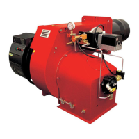
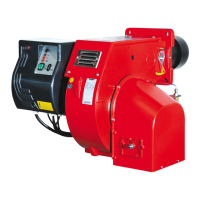
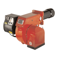
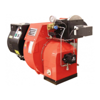
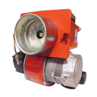
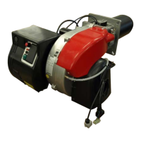
Burner description
The MAX burner is one-stage, fully-
automatic monoblock type burners.
Burner head is designed to get the lowest
emissions in terms of NOx and unburnt
particles in order to maximize the heat
generator efficiency. Emissions can be
different respect to the ones recorded in
the lab because they depends a lot on the
generator on which the burner is fit.
The installer must comply with compulsory
rules. Avoid for instance dangerous
atmosphere or not ventilated rooms.
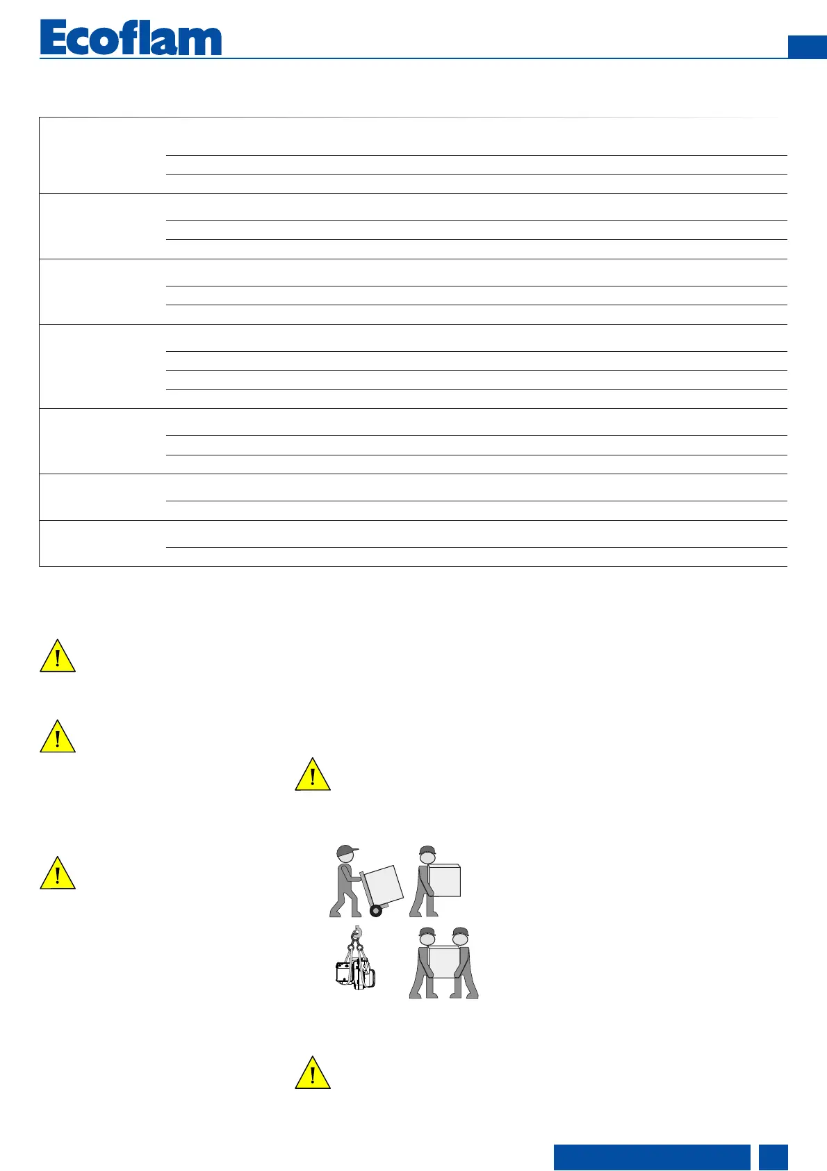
Packaging and handling
Move the burner still in its packaging using
a trolley or forklift, taking care not to drop it
and elevating it no more than 20cm from
ground level. After having removed the
packaging, check that the contents are in
good condition and correspond with what
was ordered. If in doubt, contact the
manufacturer.
The burner must be installed by a
qualified individual.
If the weight and dimensions do not allow
for manual lifting, ask another operator for
help or use a forklift, harness the burner
using belts if no eyebolts are available.
Use the accessories provided
(flange, gasket, pins and nuts) to
install the burner onto the boiler,
taking care not to damage the
isolating gasket.
We can accept no warranty liability
whatsoever for loss, damage or injury
caused by any of the following:
- Inappropriate use.
- Incorrect assembly or repair by the
customer or any third party, including the
fitting of non-original parts.
Provision of the system and the
operating instructions
The firing system manufacturer must
supply the operator of the system with
operating and maintenance instructions on
or before final delivery. These instructions
should be displayed in a prominent
location at the point of installation of the
heat generator, and should include the
address and telephone number of the
nearest customer service centre.
Notes for the operator
The system should be inspected by a
specialist at least once a year. It is
advisable to take out a maintenance
contract to guarantee regular servicing.
 Loading...