10|
×1
A12
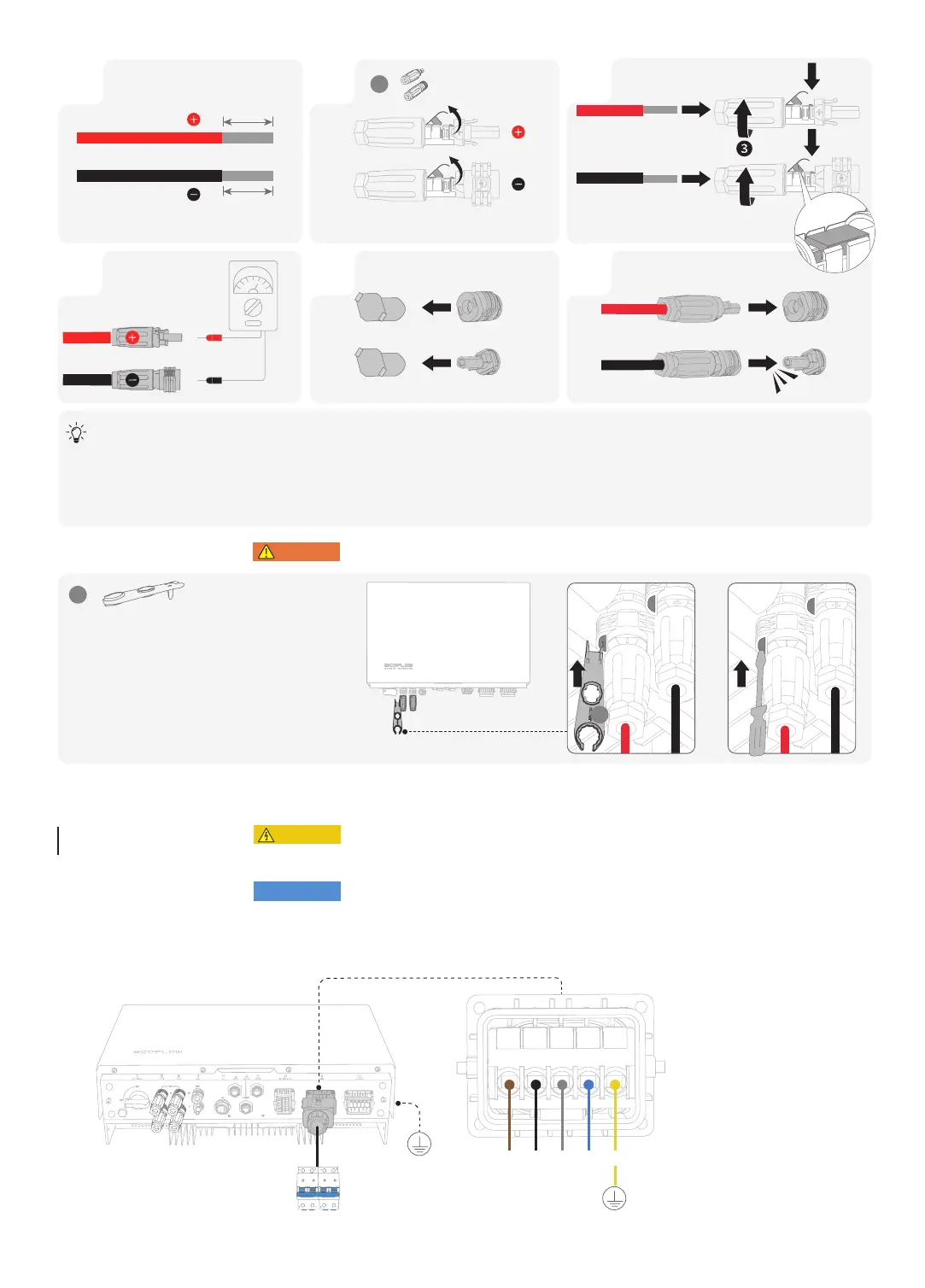
Set the multimeter to DC gear to measure the voltage at the DC position. If the voltage is a negative value, the PV input polarity
is incorrect and needs correction. If the voltage is greater than 1000 V, too many PV modules are configured to the same string.
Remove some PV modules.
If the PV input cable is reversely connected and the PV SWITCH is set to ON, first set the PV SWITCH to the OFF position, then remove
the positive and negative connectors, and correct the polarities of the PV input cables.
• Before removing the positive and negative connectors, ensure that the PV SWITCH is OFF.
L1
· a-phase line 1
L2
· b-phase line 2
L3
· c-phase line 3
N
· Neutral wire
PE
· Ground wire
L1 L3 N
PEL2
A12
4
Ensure that the cable
polarities are correct.
31 2
Ensure that the cable cannot be pulled out after
being crimped.
5
Remove Protective cap.
6
PV1+PV1+
PV1-PV1-
8-10mm
8-10mm
×1
A5
❷❶
• Before installing, operating, and maintaining the equipment, always disconnect it from all power.
• Do not connect loads between the inverter and the AC switch that directly connects to the inverter.
• Ground the PE hole of GRID connector and the equipment enclosure.
• Do not connect the GRID connector to the BACKUP terminal of the inverter.
• RCD with rated residual operating current of 100 mA(AC-GRID(and 30mA (AC-BACKUP) would
be recommended if there is additional protection by RCD shall be provided for local electrical
installation, while the use of an RCD with lower rated residual operating current is also permitted if it
is required by the specific local electrical codes.
Connecting
GRID Cables