|15
En
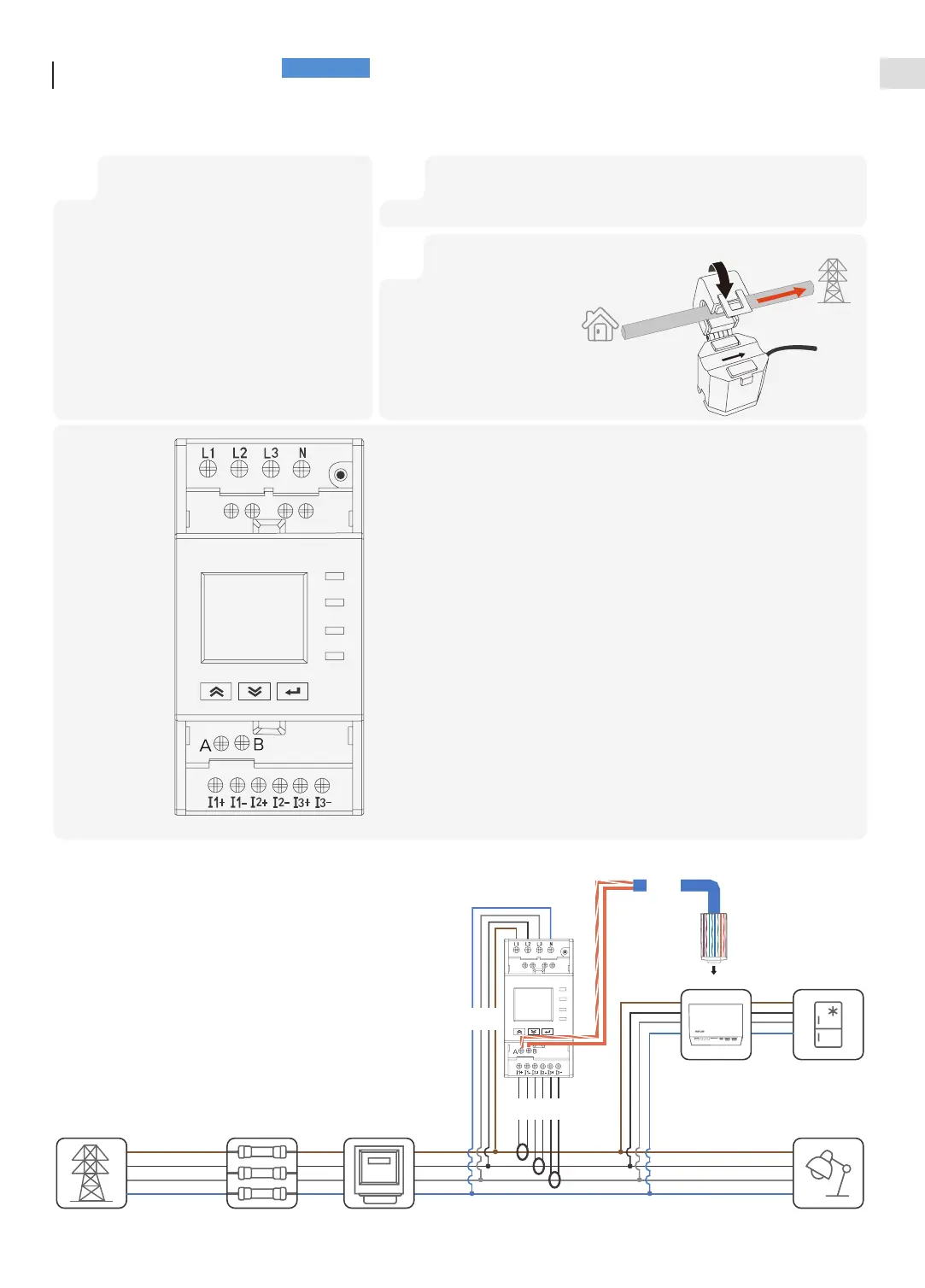
• It is recommend to use of CAT5 or higher network cable.
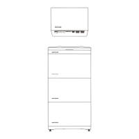
• Please use the smart meter included in the box.
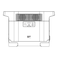
Connecting
Smart Meter
Grid a-phase CT
Grid b-phase CT
Grid c-phase CT
RS485 A(+)
RS485 B(-)
Grid a-phase voltage sampling
Grid b-phase voltage sampling
Grid c-phase voltage sampling
Neutral pole
1 2
Assembly crystal terminal in accordance with
the 586B standard and connect to the METER
port of the inverter.
Peel off the other end of the cable,
respectively, to reveal the orange and white,
orange wires.
Connect the orange and white, orange wires
to the terminal A(+), B(-) of smart meter
(install the tubular terminal at the end of wire
if needed). Refer to the following figure line 1
Refer to line 2 below, terminal 1, 2, and 3 are wired to phase a, b, and c,
respectively, to complete the voltage sampling.
3
Refer to line 3 in the
figure below, terminal
I1+, I1- are wired to
a-phase CT,terminal
I2+, I2- are wired to
b-phase CT,terminal
I3+, I3- are wired to
c-phase CT.
House
Grid
3
2
Meter Port
1