Installation using buffer storage tanks
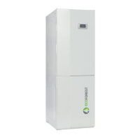
If required by the application, the heat pump can also be connected to the heating / cooling system using a buffer separator tank. To
do so, it is equipped with two temperature probes that are used to control a buffer storage tank for heating and a buffer storage tank
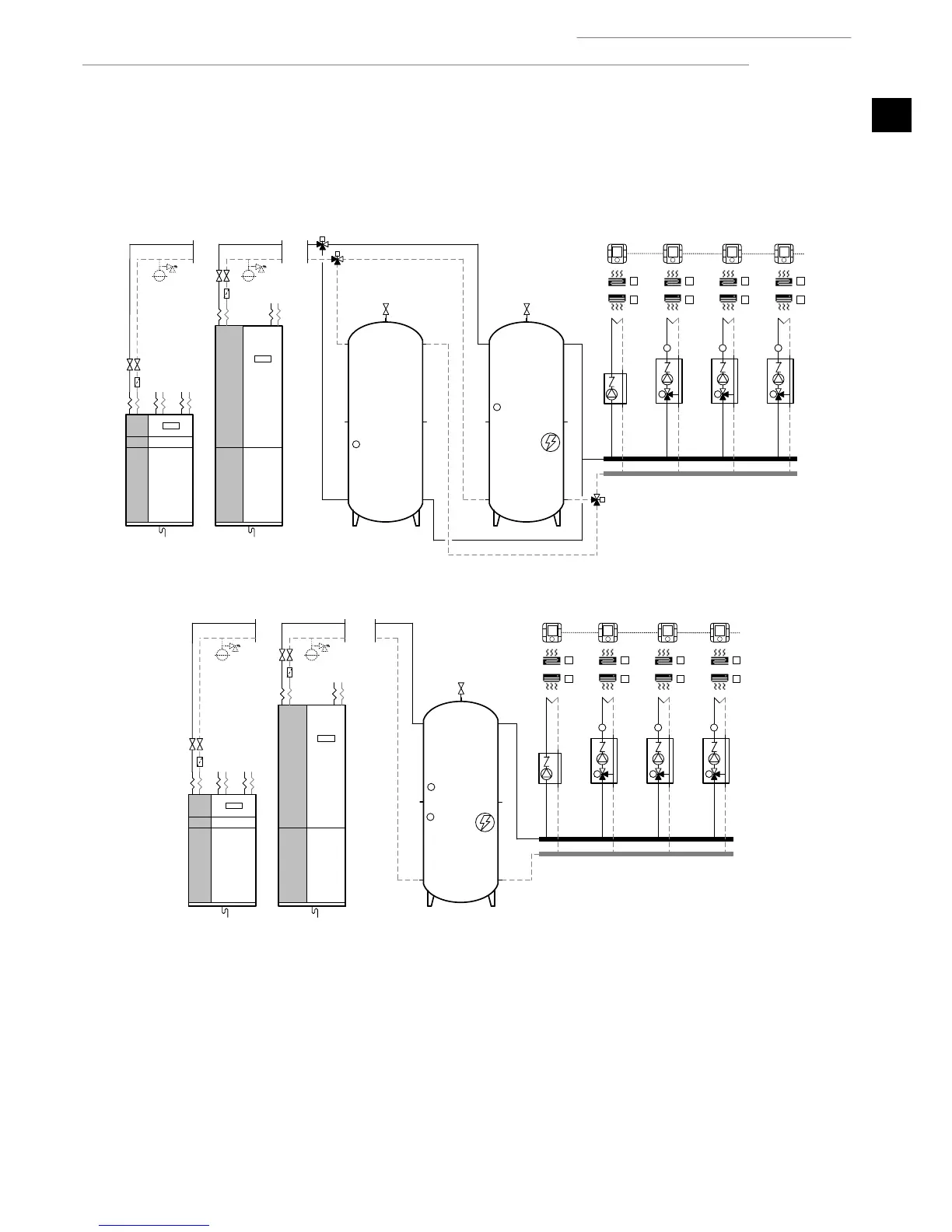
for cooling. In installations where there is only one buffer storage tank for heating and cooling, both probes have to be installed in
the storage tank. Install the temperature probes at the points where heating / cooling production begins. Heating / cooling production
is stopped by the return temperature probe installed inside the heat pump.
Figure 1.10. Wiring scheme using two buffer storage tanks.
Figure 1.11. Wiring scheme using a single buffer storage tank.
Outlet units
These can manage as many as four different outlet temperatures. This is done by managing one direct outlet unit and three combined
outlet units. The combined outlet units have to use modulating 3-way valves with an analogue signal of 0-10Vdc. Each outlet unit has
independent terminals for heating and cooling demands. These signals are supplied with 24Vac or 24Vdc voltage.