econ sens3 – operating instructions Page 2 of 4 EN
The econ sens3 multifunctional measuring instrument is capable of 1-, 2-, or 3-
phase measurements and can be used in two-wire, three-wire or four-wire TN,
TT and IT networks.
The type of connection selected for the intended use is to be chosen by the
user.
Figure 3 on page 3 displays a typical connection example with the type of
connection suitable for a 3-phase four-wire system. Other connection examples
are provided in the manual of the econ sens 3.
Connecting the supply voltage:
All required information is provided in the Technical Data.
The shielding of the connection cables described here applies to all data
interfaces of the econ
sens3. These are:
- Modbus RTU interface
- Multiple IO ports
The date lines are to be attached to both cable ends extensively and with low
impedance.
The exposed shield of the data cable is to be attached to a suitable earthing
point of the control cabinet, preferably by means of a shield bus, as displayed in
figure 5 on page 3. Further information on the functional earthing of the device is
provided in chapter 5.9 of the manual.
When using the network analysis function of the device, it is necessary to
connect the secondary GND connection with the protective earth conductor at
the “MODBUS” clamping point. This function-related earthing increases the
measuring accuracy when recording specific events on the network.
Caution: Do not earth the GND connection of the Multi-IO clamping point. It
is galvanically isolated from the GND of the MODBUS!!!
Requirements for commissioning
The instrument is mounted properly as described in chapter 5 of the manual.
The instrument is connected in accordance with the possible connection types
and taking into consideration the precautionary measures and technical
parameters according to chapter 6 and 11.
The Ethernet cable is connected.
Commissioning steps
1.) Checking the connections
Before activating the instrument, it is to be ensured that all cable connections to
the econ sens3 have been produced as described in chapter 5 of the manual
and that the connected voltage values of the inputs do not exceed the values
indicated in the technical data
2) Applying the supply voltage
3) Applying the measuring voltage
4) Applying the current measurement
5) Parametrization of the instrument
6) Checking the measuring values for plausibility
The econ sens+ includes a small installation checking routine, called "Installation
check". It is described in chapter 8 of the manual.
econ sens+ basic instrument
Conditions for transportation and storage
The following information applies to instruments which are transported
and stored in their original packaging.
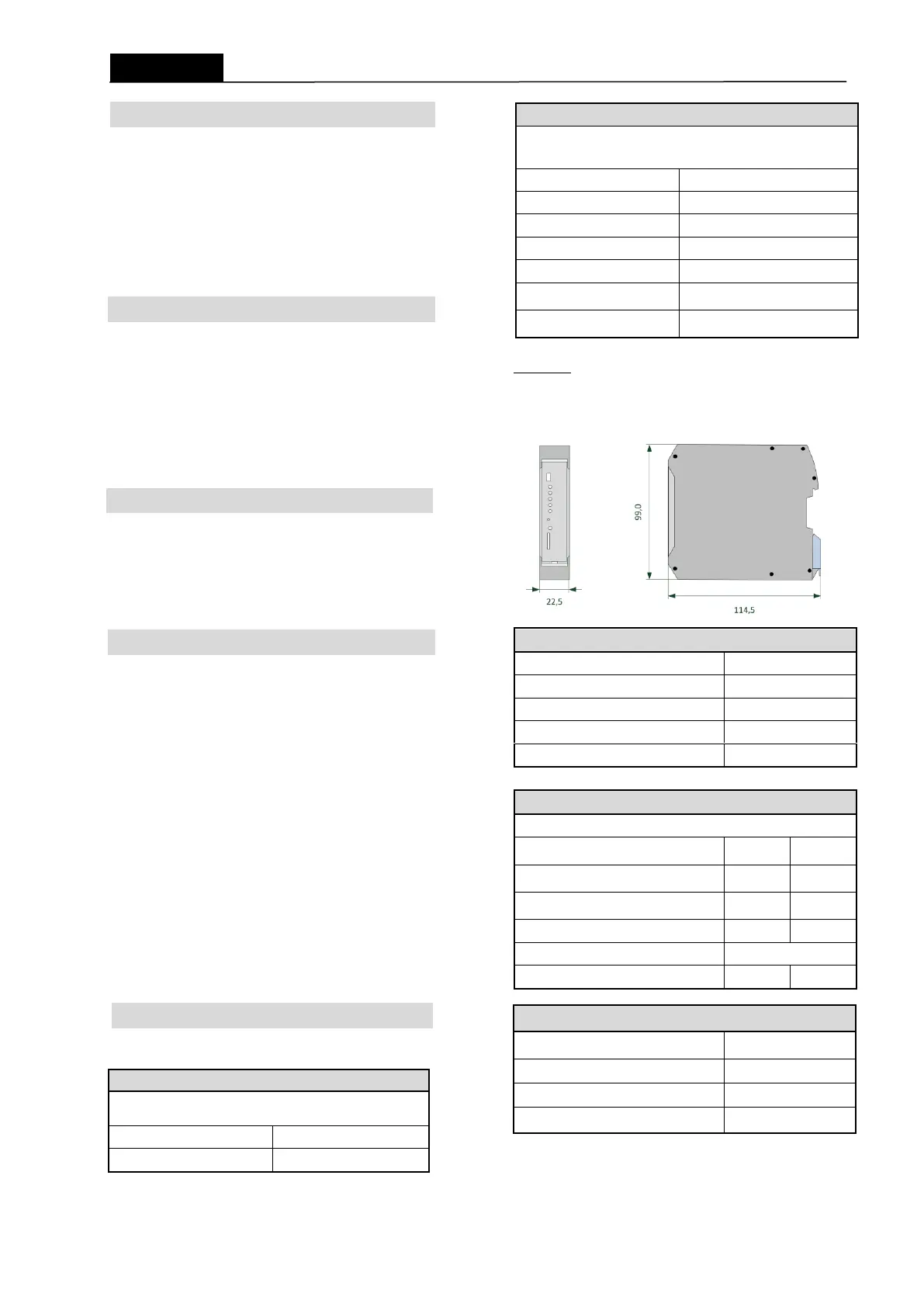
Dimensions:
Commissioning / parameterization of the instrument
Ambient operating conditions
The econ sens3 power meter is intended for a weather-protected, stationary
operation within closed rooms.
Nominal temperature range
0 to 75 %, non-condensing
Operating altitude above NN
horizontal on mounting rail*
Distance towards adjacent devices, 6
mm* on both sides
Protection class according to IEC
60529
If the application requires a greater
protection class, suitable measures are to be implemented by
the customer
Installation overvoltage category
Protection of the supply voltage
Connection capacity of the "AC supply voltage" clamping point
Plug connector, pluggable MSTBT 2.5HC/4 screw terminal
rigid, multi-wired or fine-wire conductors
without ferrule [mm²]
fine-wire with ferrule
with/without plastic collar [mm²]
fine-wire with TWIN ferrule
with plastic collar [mm²]
Min./max. AWG conductor cross-sections
Min./max. tightening torque [Nm]
Protection of the supply voltage
(safety device)
Earthing/shielding of the data lines
Earthing of GND connection (network analysis)
 Loading...