Do you have a question about the Econ sens3 and is the answer not in the manual?
Explains the different warning levels (Danger, Warning, Caution, Attention) and their associated meanings and implications.
Details the safety symbols found on the instrument, specifically for electrical shock and general warnings.
Provides a table explaining the meaning of various safety symbols used throughout the manual.
Specifies the authorized applications and limitations of the econ sens3 measuring instrument.
Specifies safe locations and access requirements for instrument installation, emphasizing qualified personnel access.
Emphasizes critical safety precautions, including dangers of high voltage and requirements for qualified personnel.
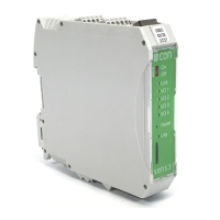
Shows a diagram of the instrument's connection terminals and provides a general warning about incorrect connections.
Explains how to connect the instrument for voltage measurement, including circuit diagrams and safety notes.
Describes how to connect the instrument to the main power supply and auxiliary voltage, including disconnect device requirements.
Explains how to connect Rogowski coils for current measurement and safety precautions for live parts.
Covers connecting the instrument via Ethernet, including Modbus TCP, network diagrams, and cable recommendations.
Explains how to connect the instrument using the Modbus RTU protocol, including network topology and bus termination.
Details how to use the multiple I/O ports for data transfer, defining them as inputs or outputs.
Covers grounding and shielding procedures for Modbus RTU, I/O, and Ethernet cables to minimize disturbances.
Illustrates connection diagrams for 3-phase/4-conductor, 3-phase/3-conductor, and 1-phase systems.
Outlines the necessary conditions and step-by-step guide for the first-time operation of the instrument.
Guides users on how to access and connect to the instrument's web interface using its IP address.
| Brand | Econ |
|---|---|
| Model | sens3 |
| Category | Measuring Instruments |
| Language | English |