Display and control elements 33
Manual econ sens3 Version 3.0
6 Display and control elements
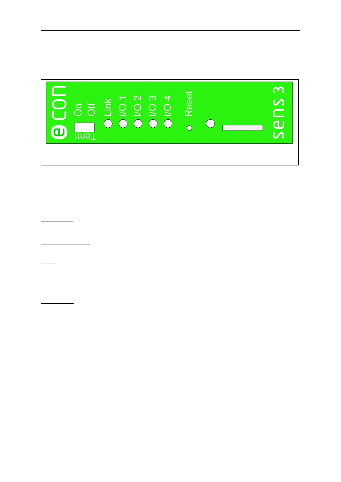
Figure 27 shows the arrangement of the display and control elements of the econ sens3.
“TERM On/Off”: Activates/deactivates termination of the Modbus interface. More information
on bus termination is found in Chapter 5.7.
LED “Link”: Lights up when connection to the network is active. The LED starts blinking as
soon as data transfer to/from the instrument occurs.
LED “I/O1 to I/O4”: The LEDs I/O1 to I/O4 show the status of the respective I/O port.
Reset: Reset button to perform a “factory reset.”
The reset is a 4-stage reset. More information on the reset is found in Chapter
9.4.
LED “LOG”: Blinks as soon as the instrument is ready to log data.