EasyManua.ls Logo

Ecoplus SBR-12.5H-B - User Manual

Ecoplus SBR-12.5H-B
24 pages
Print Icon
To Next Page IconTo Next Page
Loading...
SBR-12.5H-B SBR-17.0H-B-S
Question and Answer IconNeed help?

Do you have a question about the Ecoplus SBR-12.5H-B and is the answer not in the manual?

Summary

Safety and Warnings

Important Warnings

Critical safety advice for appliance usage, including child supervision, fuse, wiring, and operational ranges.

Product Specifications

Performance Data

Detailed performance specs including capacities, ranges, input power, COP, and EER.

Product Dimensions

Unit Dimensions

Diagrams and table showing physical dimensions (A-H) for different models.

Wire Controller Operation

Controller Introduction

Overview of the controller display and its components.

Button Definitions

Explains the functions of ON/OFF, SET, TIMER, MODE, UP/DOWN buttons.

Parameter Data Setting

Steps to check and change settings on the controller, including data flashing.

Clock and Timing Settings

Guides for setting the real-time clock and automatic ON/OFF timers.

Power Resumption Memory

Explains how the unit retains settings after a power interruption.

Parameters

Adjustable Parameters

Table listing adjustable parameters (SET0, SET1, etc.) with their ranges and defaults.

Troubleshooting

Failure Codes

Lists protection/failure codes (PP, EE) and their associated issues.

Wi-Fi Connectivity

First Way: App Connection (Android;iOS)

Steps to connect via SmartLink3 Demo app (Android) or SmartLink app (iOS).

Second Way: Direct Connection

Connecting directly to the heat pump's Wi-Fi, configuring STA mode, and selecting networks.

Wi-Fi Connection Remarks

Notes on saving settings, IP changes, and restoring default Wi-Fi settings.

Fast Inquiry Website

Information on accessing heat pump status via a website or QR code.

Maintenance

Water Supply and Filter

Regular checks of water supply, filter, and avoiding air/no water conditions.

Environment and Electrical Checks

Maintaining a dry, sanitary environment and checking power connections for issues.

Winterization Procedures

Procedures for draining water to prevent freezing during long shutdowns.

Wiring Diagrams

SBR-12.5 H-B Wiring

Electrical schematic showing connections for the SBR-12.5H-B model.

SBR-17.0 H-B-S Wiring

Electrical schematic showing connections for the SBR-17.0H-B-S model.

Service and Support

Obtaining Service (Pool Owner)

Information required by pool owners when contacting for service.

Obtaining Service (Installing Dealer)

Steps for installing dealers to obtain service for customers.

Freon Information

Explains that refrigerant should not need refilling unless there's a leak.

System Evaluation Charts

Outdoor Pool Charts

Charts showing average pool temperature and energy flows for outdoor pools.

Indoor Pool Charts

Charts showing pool temperature and space temperature for indoor pools.

Installation Guidelines

Unit Installation Position

Diagrams showing recommended clearance and placement for unit installation.

Installation Attachments

Heat Pump & Chlorinator Setup

Diagram illustrating the setup of a heat pump with a pressure-type chlorinator.

Unit Conversions

Common Units Conversion

Tables for converting linear, square, cubic, capacity, weight, energy, velocity, and pressure units.

Overview

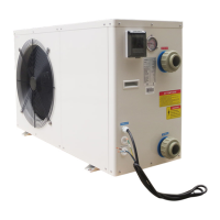
This document serves as the Installation & Instruction Manual for a SWIMMING POOL HEAT PUMP UNIT, specifically covering models SBR-12.5H-B and SBR-17.0H-B-S. It provides essential information for safe and effective operation, installation, and maintenance of the heat pump.

The primary function of this device is to heat or cool swimming pool water. It operates as a heat pump, transferring heat from one location to another, allowing for efficient temperature control of the pool. The unit is designed for both heating and cooling modes, offering flexibility for various ambient conditions and desired pool temperatures.

Usage Features:

The heat pump is controlled via a wire controller, which features an LCD display showing key operational data such as heating mode, water outlet temperature, water inlet temperature, and the current time.

  • Turning On/Off: The heat pump can be turned on or off using the dedicated "button" on the wire controller.
  • Temperature Setting: Users can set the desired water temperature. In heating mode, the outlet water temperature can be set within a range of 20~40°C. In cooling mode, the outlet water temperature can be set between 8~28°C.
  • Clock Setting: The wire controller allows for setting the real-time clock. By pressing the "button" repeatedly, users can adjust the hour and minute data using the "up" and "down" buttons, and then confirm the setting.
  • Timing ON/OFF: The unit supports scheduled operation. Users can set specific times for the heat pump to turn on or off, integrating with the "up" and "down" buttons for time adjustments. This feature allows for automated operation, optimizing energy use.
  • Parameter Data Setting: The controller enables checking and changing various parameters. By pressing the "up" or "down" button, users can select a parameter, and when the "icon" appears, the data can be changed using the "up" or "down" buttons, then confirmed with the "button". This includes settings for cold water set point, hot water set point, auto backwater set point, and tank water set point.
  • Force Defrost: In standby status, pressing the "M" button for 3 seconds can initiate a Force Defrost cycle, which is useful for maintaining optimal performance in certain conditions.
  • Keyboard Lock: To prevent accidental changes, the keyboard can be locked by pressing the "up" and "down" buttons simultaneously for 3 seconds.
  • Back Up Memory: The system incorporates a back-up memory feature. In the event of a power cut during normal operation, the heat pump will resume operation with the last saved settings once power is restored.
  • Error Codes: The wire controller displays specific failure codes (e.g., PP1, EE1) to indicate various protection or failure conditions, such as sensor failures, pressure issues, or water flow problems, aiding in troubleshooting.
  • Wi-Fi Connectivity: The heat pump offers Wi-Fi connectivity, allowing for remote monitoring and control via a smartphone or laptop.
    • Android System (First Method): Users can install the "SmartLink3 Demo" APP, ensure the heat pump is on and within Wi-Fi signal range, and connect their smartphone to the local Wi-Fi. By long-pressing the ON/OFF and DOWN buttons on the LCD controller for 10 seconds, the unit enters a pairing mode. Users then input their local Wi-Fi password into the app to connect. A "SmartLink completed" message indicates success, while "Time Out!" suggests a retry is needed.
    • IOS System (First Method): For iOS users, the "SmartLink" app can be found and installed from the APP Store, or by scanning a provided QR code. The process then involves inputting the local Wi-Fi password to connect.
    • Second Method (Laptop/Smartphone via Web Interface): Alternatively, users can connect to the heat pump's dedicated Wi-Fi network ("HF-LPB100") using a laptop or smartphone. By accessing a specific IP address (10.10.100.254) in a web browser and logging in with default credentials (username: admin, password: admin), users can configure the Wi-Fi settings. This involves changing the work mode to "STA mode," scanning for available local networks, selecting a secure network, and inputting the network's password, ensuring WPA2PSK encryption and AES algorithm are selected. After saving the settings, a system restart is required to apply the changes.
  • Fast Inquiry: Once connected to Wi-Fi, users can inquire about the heat pump's status via a provided website link or by scanning a QR code. This allows for quick checking of 1 or 2 heat pump units.
  • Agent Research: For checking multiple heat pumps, another website link is provided for "Agent research."

Maintenance Features:

Regular maintenance is crucial for the longevity and efficient operation of the swimming pool heat pump.

  • Water Supply Device Check: It is important to frequently check the water supply device to prevent conditions like no water or air entering the system, which can negatively impact performance and reliability.
  • Water Filter Cleaning: The water filter should be cleaned regularly to prevent clogging, which could damage the unit.
  • Unit Environment: The area around the unit should be kept dry, sanitary, and well-ventilated.
  • Condenser Cleaning: The side condenser needs to be cleaned regularly to ensure good heat exchange and energy efficiency.
  • Electrical Component Check: Users should periodically check the power supply and cable connections for any abnormal activity or unusual smells from electrical components. If any issues are detected, the installer should be contacted immediately.
  • Winterization/Long-Term Storage: If the unit is to be stopped for a long period, especially during colder seasons, all water in the water pump and water system must be discharged to prevent freezing. Before restarting the units, they should be thoroughly checked, and the system fully refilled with water.
  • Refrigerant System: The factory charge of freon is designed to last the life of the unit, assuming no leaks in the sealed refrigeration system. Freon is stable and should not degrade. If the unit requires freon, it indicates a leak that must be located and repaired, as simply adding freon will not solve the underlying problem. Freon leaks are generally uncommon and often result from shipping damage.

The manual emphasizes that installation and maintenance should be performed by technical personnel to prevent damage or hazards. Customers are advised to contact installation service for reference.

Ecoplus SBR-12.5H-B Specifications

General IconGeneral
HSPF9.0
RefrigerantR410A
Noise Level52 dB
Cooling Capacity12, 500 BTU/h
Voltage208-230V, 60Hz, 1Ph

Related product manuals