Page 7
Diagram #1
STEP 4B. Follow this step only if you are also installing a S10 sediment, C6 carbon, or Fe6 iron removal
pre-filter(s) with your ecoTAC unit.
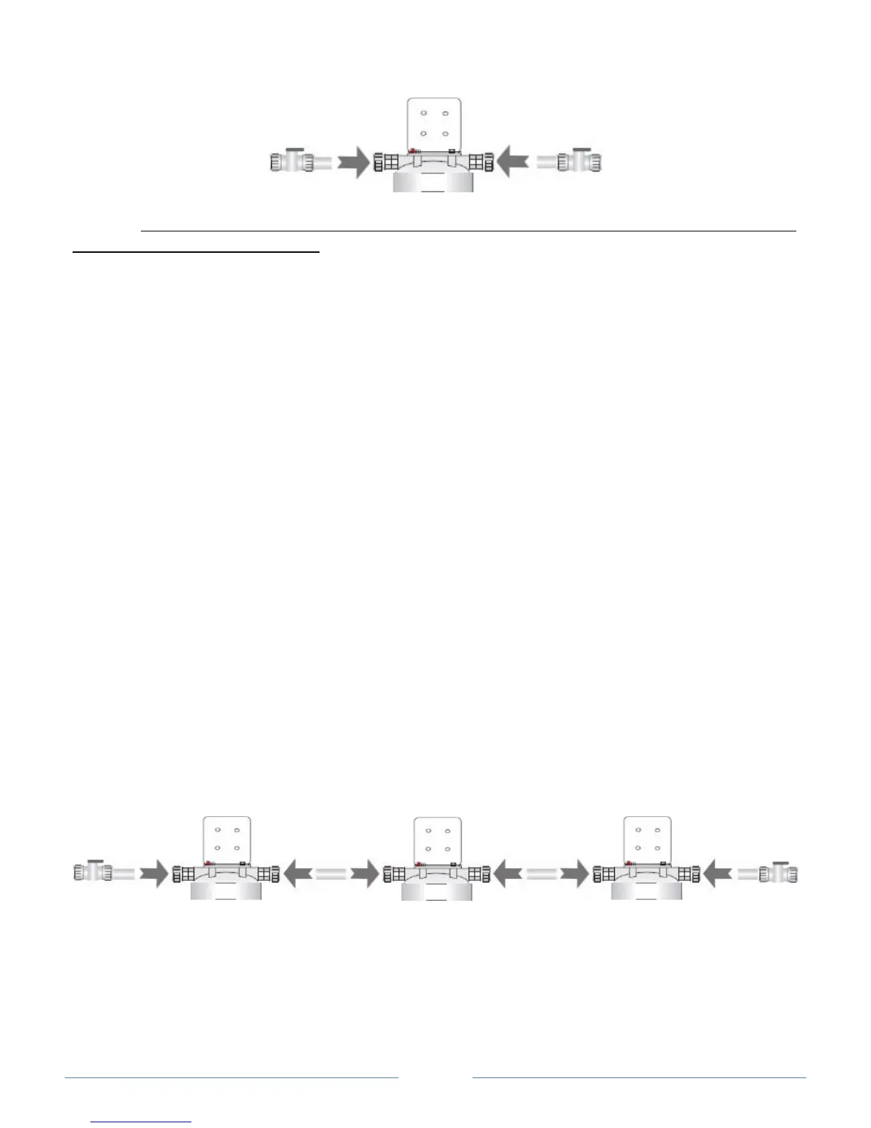
Assemble the components according to Diagram #2 below in the following sequence:
S10 Sediment Pre-Filter Package or Similar (if equipped)
Fe6 Cartridge-Based Iron Reduction Filter (if equipped)
C6 Activated Carbon Pre-Filter or Similar (if equipped)
ecoTAC Salt-Free Hard Water Conditioner
Start by taking the quick-connect shut-off valve assembly labeled “IN” and pushing it into the quick-
connect fitting on the inlet side of the first housing cap (“IN” is embossed on top of the white cap on the
inlet side). Turn the collar on the quick-connect fitting clockwise roughly 1/4 turn to lock the fitting.
Connect this housing cap to the next housing in the sequence using the PEX tube from the pre-filter
package in the same manner. Make sure that you are always connecting the outlet of one housing cap
to the inlet of the other. Don’t forget to lock each fitting by turning the collar on the quick-connect
fitting 1/4 turn. Repeat as necessary until all of the housing caps are connected. When you are done,
check to be sure that the inlet and outlets of each housing are connected in the correct sequence.
Finally, take the other quick-connect shut-off valve assembly labeled “OUT” and connect it to the quick-
connect fitting on the opposite side of the last housing cap and lock it into place in the same manner.
Attach the mounting brackets to each housing cap using the 4 fasteners provided, then securely mount
the housings to the wall using wood screws. Check to make sure the brackets are level. If you are
securing the system to drywall or plaster, be sure that the wood screws reach a wood stud, or
alternatively, install appropriate anchors for secure support. Be sure to allow enough space below the
housing caps to accommodate the white housing sumps plus a minimum of an additional 3 inches of
clearance.
Diagram #2
STEP 5. Make the appropriate plumbing connections between the inlet and outlet shut-off valves and
your plumbing lines using appropriate union fittings where necessary. 3/4” PEX, Copper*, or CPVC
tubing (see required specifications above) can be push fit to the shut-off valves on the inlet and outlet of
the system in the same manner as the previous connections. *While copper can be used, it is not
recommended.
 Loading...