Page 6
other water treatment equipment. If this filter is used after a chlorinator, you should install the C6
Activated Carbon Pre-Filter to protect the filter from excess chlorine which can harm the media.
STEP 2. Shut off the main water supply and drain the pipes. Opening the highest and lowest fixtures in
the house will help drain the pipes. WARNING. If you have an electric water heater (tankless or
conventional), TURN OFF all power to the water heater before proceeding. If you fail to do this, you
may cause severe permanent damage it its heating elements.
STEP 3. Using a pipe cutter, cut out a section of your main water line at the point where you want to
install your filter system. There will probably be some water remaining in the system, so be sure to have
a bucket and some rags handy to clean up any small spills. Make sure that the section of water line you
remove is appropriately sized such that all of the components of the system including the shut-off-
valves, adapters, and the blue filter cap(s) will fit snuggly when assembled. If in doubt, cut a smaller
section at first – you can always remove a slightly larger section upon final assembly if necessary.
STEP 4.
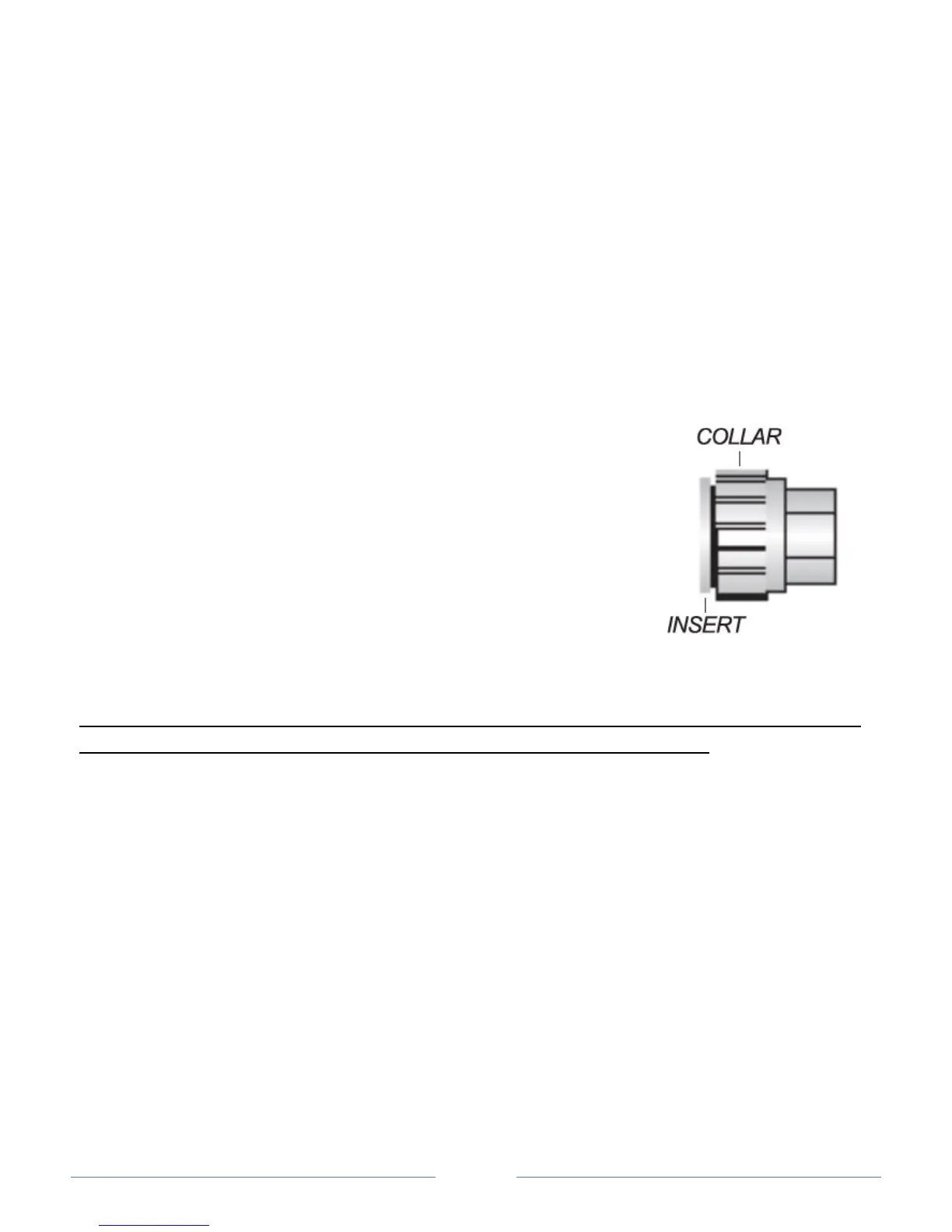
It is now time to assemble the system. Your ecoTAC™ unit is supplied
with quick-connect fittings for your convenience. These fittings do not
require any tools or sealants (Teflon, etc.) These fittings connect by
pushing the pipe into the fitting approximately 1 1/2” until it stops and
turning the collar 1/4 turn clockwise to lock the fitting in place. An o-ring
inside the fitting forms a tight seal on the pipe and teeth inside the
fitting prevent the fitting from disconnecting under pressure.
In the event that the fitting ever needs to be removed, you simply
turn the collar 1/4 turn counter-clockwise, depress the fitting insert
squarely against the fitting to release the teeth, and pull out on the pipe.
If you are installing a S10 sediment, C6 carbon, or Fe6 iron removal pre-filter with your
ecoTAC™ unit, please go to Step 4B, otherwise continue with Step 4A.
STEP 4A. Assemble the components according to Diagram #1 below. Start by taking quick-connect
shut-off valve assembly labeled “IN” and pushing it into the quick-connect fitting on the inlet side of the
housing cap (“IN” is embossed on top of the white cap on the inlet side). Turn the collar on the quick-
connect fitting clockwise roughly 1/4 turn to lock the fitting. Take the other quick-connect shut-off
valve assembly labeled “OUT” and connect it to the quick-connect fitting on the opposite side of the
housing cap and lock it into place in the same manner. Attach the mounting bracket to the housing cap
using the 4 fasteners provided, then securely mount the housing to the wall using wood screws. If you
are securing the system to drywall or plaster, be sure that the wood screws reach a wood stud, or
alternatively, install appropriate anchors for secure support. Be sure to allow enough space below the
housing cap to accommodate the white housing sump plus a minimum of an additional 3 inches of
clearance.
 Loading...