EasyManua.ls Logo

Ecreso HELIOS Series - User Manual

Ecreso HELIOS Series
127 pages
Print Icon
To Next Page IconTo Next Page
Loading...
ecreso WorldCast Systems Group
web: www.ecreso.com - e-mail: contact@ecreso.com
HELIOS TRANSMITTER
20, 50 or 100 W
USER MANUAL
OPTIONS: TUN – CSS - CSS+ - CSSN - TC/S/N - CAN/X – IP/CAN – IP/CAN/X
Date: 2011/01/14
Ref : DOE00012

Table of Contents

Question and Answer IconNeed help?

Do you have a question about the Ecreso HELIOS Series and is the answer not in the manual?

Overview

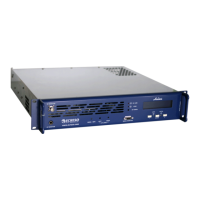
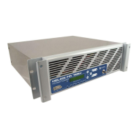
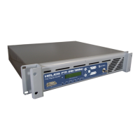
The Ecreso Helios transmitter is designed for FM mono, stereo, or multiplex program transmission within the 87.5 to 108 MHz frequency range, offering output power options of 20, 50, or 100 watts into 50 ohms. It is a standard 19-inch 2U device, suitable for rack mounting, and can be equipped with an internal stereo coder (CSS, CSS+, or CSSN plug-in cards) or connected to an external coder. The transmitter supports optional Remote Control (RC) and Remote Monitoring (RM) cards for enhanced management.

Function Description

The Helios transmitter's core function is to generate an FM carrier signal for audio transmission. It processes audio signals from mono/MPX and auxiliary inputs, applying pre-emphasis and filtering before sending them to a synthesizer. The synthesizer generates the FM carrier, which is then amplified by an RF amplifier block. This block includes a heat sink, coolers (one for 50W, two for 100W), MOS-FET transistors, and monitoring electronics to ensure stable output power and protection against overheating or high VSWR. The main board also integrates an RDS demodulator and connections for various optional cards.

The optional stereo coder cards (CSS, CSS+, CSSN) enable stereophonic multiplex signal transmission. The CSS and CSS+ cards handle analog left and right audio inputs via XLR sockets, while the CSSN card supports digital AES/SPDIF inputs. These cards generate the 19 kHz pilot tone and the MPX output signal.

Remote control and monitoring capabilities are provided by optional RC/RM boards. These boards offer functionalities such as on/off control, power control, recall of memorized configurations, reset, and alarm reporting (3dB alarm, VSWR alarm, temperature alarms). They interface with external systems via serial ports (RS-232, RJ11) or Ethernet (RJ45 for IP/CAN cards), allowing for local or distant management.

Important Technical Specifications

RF Section:

  • Frequency Range: 87.5 to 108 MHz
  • Frequency Steps: 10 kHz
  • Frequency Stability: < 10⁻⁶ per year
  • Power Range:
    • 20 W version: 2 to 20 W @ TOS=1.35
    • 50 W version: 5 to 50 W @ TOS=1.35
    • 100 W version: 10 to 100 W @ TOS=1.35
  • Power Output:
    • 20 W version: continuously from 0.1 to 24 W
    • 50 W version: continuously from 0.1 to 60 W
    • 100 W version: continuously from 0.1 to 120 W
  • Spurious and Harmonic Suppression: > 75 dBc (87.5 to 137 MHz), > 70 dBc (out of band)

Composite Operation:

  • Bandwidth: > 40 Hz to 55 kHz @ 0.2 dB, > 20 Hz to 100 kHz @ 0.4 dB
  • Intermodulation Distortion: < 0.05%
  • FM S/N Ratio: > 70dB RMS @ 75 kHz deviation
  • AM Noise: < 1% (40 dB) RMS (20-20,000 Hz)

Stereo Operation (with CSS, CSS+, CSSN Coder Cards):

  • Bandwidth: > 40 Hz to 15 kHz @ 0.5 dB
  • 38 kHz Discontinuance: > 50 dB
  • Stereophonic Separation: > 40 dB
  • Pre-emphasis: 0 µs, 50 µs, or 75 µs

Mono Operation:

  • Bandwidth: > 40 Hz to 15 kHz @ 1 dB
  • Out of Band Rejection: > 30 dB @ 19 kHz
  • Pre-emphasis: 0 µs, 50 µs, or 75 µs
  • With CSS+, CSSN Coder Cards: Bandwidth > 40 Hz to 15 kHz @ 0.5 dB, Out of band rejection > 35 dB @ 19 kHz

AF Inputs:

  • Auxiliary (AUX) (BNC): Impedance > 2 kΩ, Bandwidth > 50 kHz to 100 kHz @ 0.5 dB, Level -11 dBu @ 10% Nominal dev.
  • Mono/Multiplex (Mono/MPX) (BNC): Impedance > 2 kΩ, Level adjustable (-6 dBu to 6 dBu or 6 dBu to 18 dBu @ 75 kHz deviation)
  • AF Inputs (LEFT/RIGHT) (XLR Female, for CSS, CSS+): Impedance > 5 kΩ balanced, Level adjustable (-6 dBu to 6 dBu or 6 dBu to 18 dBu @ 75 kHz deviation)
  • AES-UER / SPDIF Inputs (XLR Female, for CSSN): Impedance > 120 Ω AES-UER / 75 Ω SPDIF, Level adjustable (-6 dBu to 6 dBu or 6 dBu to 18 dBu @ 75 kHz deviation)

BF Output (On Helios):

  • Multiplex Output (MPX) (BNC): Impedance < 50 Ω, Level 10 dBu @ 100 W
  • 19 kHz Output (BNC, on coder cards): Impedance < 50 Ω, Level 1 V peak to peak, Square, no DC

Power Supply:

  • Voltage: 20/50 W versions: 88-132 VAC or 176-264 VAC (selectable); 100 W version: 88-264 VAC
  • Frequency: 47 Hz - 63 Hz
  • Consumption: < 60 W (20 W), < 150 W (50 W), < 300 W (100 W)
  • Fuses: 1.5 AT (20/50 W), 2 AT (100 W)

Physical:

  • Dimensions: 19’’ (482.6 mm) X 2U (88.9 mm) X 530 mm
  • Weight: 10 kg
  • Cooling: Natural convection (20 W), internal ventilation (50/100 W)

Usage Features

The Helios transmitter operates in two main modes: LOCAL and DISTANT.

  • LOCAL mode: This is the maintenance mode, allowing modification of all settings (transmission frequency, output power, input levels, RDS settings, serial port speed, password). Alarms are read but not stored.
  • DISTANT mode: This is the standard operating mode. Settings are not accessible, but measurements (forward power, reflected power, VSWR, deviation, alarms) are displayed and alarms are stored in the log. Remote control cards are activated in this mode.
  • STAND-BY mode: Communication interfaces remain active, and commands are accepted, but the display switches off after 10 seconds.

Mode selection is done via the front panel LCD display and buttons. Pressing the ENTER button for 5 seconds brings up the mode menu, allowing navigation between LOCAL, DISTANT, and STAND-BY.

The transmitter features an "anti-yoyo" system that monitors internal temperature and link status. If the amplifier shuts down due to overheating three times within an hour, the device sets RF=OFF and requires a manual RF=ON command to restart, protecting the RF amplifier from damage.

The front panel includes potentiometers for adjusting mono/multiplex input level, left/right input levels (for stereo coders), and RF output power. An LCD display shows operating parameters and menus, while LED indicators provide visual feedback for synthesizer lock (green), HF alarms (red for 3dB power loss and VSWR), and maintenance mode (yellow for LOCAL).

Maintenance Features

Preventive maintenance involves dusting the unit annually. Calibration of the transmitter is recommended every 1 to 3 years. To prolong equipment life, it is advised to change fans every three years and lithium batteries (for NVRAM) every five years.

Troubleshooting guidance is provided for common issues:

  • No RF output: Check RF cables, perform a RESET, and inspect the exciter and amplifier.
  • Decreased power: Check the exciter and Goliath amplifier.
  • Maximum power not reached: Check the RF exciter and adjust the RF POWER potentiometer.
  • VSWR alarm: Inspect the antenna and cable.
  • Overheating alarm: Check the coolers.
  • Sound quality problems (stereo coder): Verify AF signals on XLR/MPX connectors and check the stereo coder card.

The manual also details how to add optional cards, emphasizing the importance of turning off the device and using appropriate tools for installation. Connections, including RF output, audio inputs, and remote control interfaces, are described with specific cable requirements (50 ohms coaxial for RF, reinforced cables for BNC, SUB-D, RJ11, RJ45). Fuse values are provided, with a note on doubling values for 115 Vac operation.

Ecreso HELIOS Series Specifications

General IconGeneral
BrandEcreso
ModelHELIOS Series
CategoryTransmitter
LanguageEnglish

Related product manuals