Vers. 2009-3
water cassettes
9
INSTALLATION, OPERATION
AND MAINTENANCE MANUAL
2%
50
CONDENSATE DRAINAGE
INSTALLATION OF AUXILIARY DRAIN PAN
ATTENTION!
CONDENSATE DRAINAGE IS FUNDAMENTAL FOR GOOD OPERATION OF
THE WATER CASSETTE. LAG THE PIPES SUITABLY AND CORRECTLY.
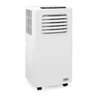
To ensure a correct fl ow of the condensed water, the water drainage pipe must
have a slope of 2% without obstructions. Install a trap at least 50 mm deep in
order to avoid unpleasant smells.
There is the possibility of draining water from 200 mm above the level of
the unit.
To drain the condensate at a higher level, install condensate drain pump with
collecting tray and fl oat valve (not included in the standard accessories). A fl oat
valve is recommended to stop the fl ow of water in the event of pump failure.
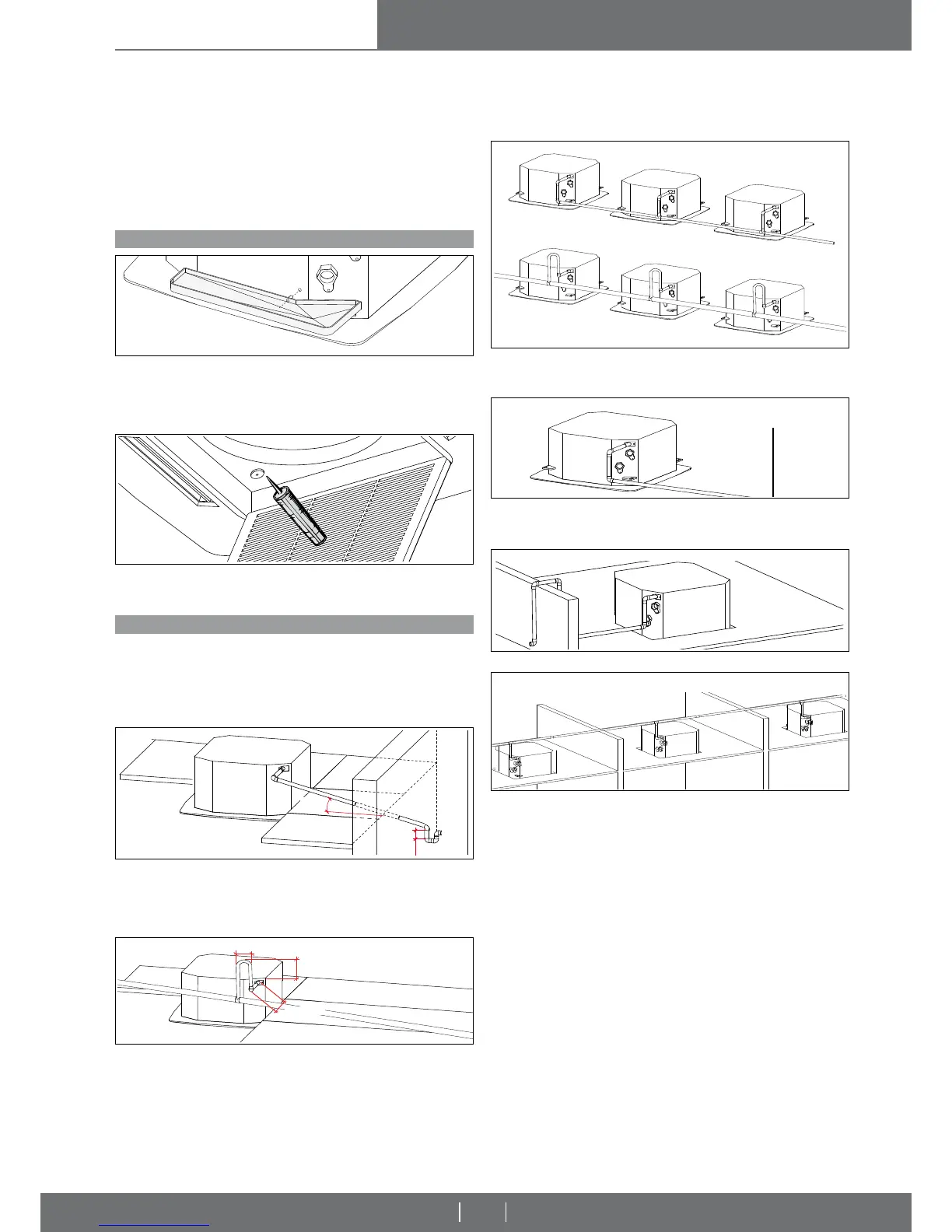
a) Remove the plastic cap from the condensate drain outlet on the water
cassette. Do NOT push the cap into the cassette.
Fit the nozzle into the hole (auxiliary condensate drain pan outlet).
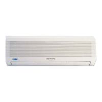
b) Fix the auxiliary drain pan to the unit using the relative screws provided in the
kit, ensuring that the condensate pan is level.
IMPORTANT!
- If the drain pan plastic cap is removed, remember to seal it with silicone
when replacing it!
ATTENTION!
- Always use suitably sized wrenches to fi x or slacken the water pipes.
- It is essential to insulate pipes, valves and connections correctly in order
toavoid the formation of condensation, which could drip into suspended
ceilings causing considerable problems.
The water connections are fi xed to the unit body to avoid damage when pi-
pes are connected. It is advisable to tighten the connection with a wrench. The
upper coil connection is fi tted with an air valve and the lower connection with
a drain valve, suitable for a 10 mm wrench or screwdriver. (The coil is only
partially drainable; it is advisable to blow air into the coil for complete drainage)
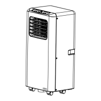
The discharge levels in pic. 15 must be strictly adhered with.
The following diagrams describe some examples of how the condensate
discharge connection can be implemented correctly (Figs. 18-19) and incor-
rectly (Figs. 20-21).
Pic. 18: when several units are installed near to each other and only one con-
densate drain hose is used, make sure that the capacity of the hose is suffi cient
and that it is positioned on a slightly lower level than the appliance.
Pic. 19: the condensate drain hose should be fi xed using intermediate mounts
to prevent deformation of the hose. The drain hose should slope slightly down-
wards to encourage drainage of the condensed water.
Pic. 21: the drain hose is on the same lever as unit.
ATTENTION!
- Ultimately verify the smooth fl ow of condensate water from the basin to
the discharge pipe (before blocking the dropped ceiling)!
- If the condensate drainage alarm is activated, the zone valve is closed
and the fan turned off.
Pic. 20: the drain hose is bent or points upwards.
Pic. 14
Pic. 15
Pic. 18
Pic. 19
CORRECT!
CORRECT!
WRONG!
WRONG!
Pic. 16
Pic. 17
< 100 mm
< 200 mm
< 100 mm
Pic. 20
Pic. 21