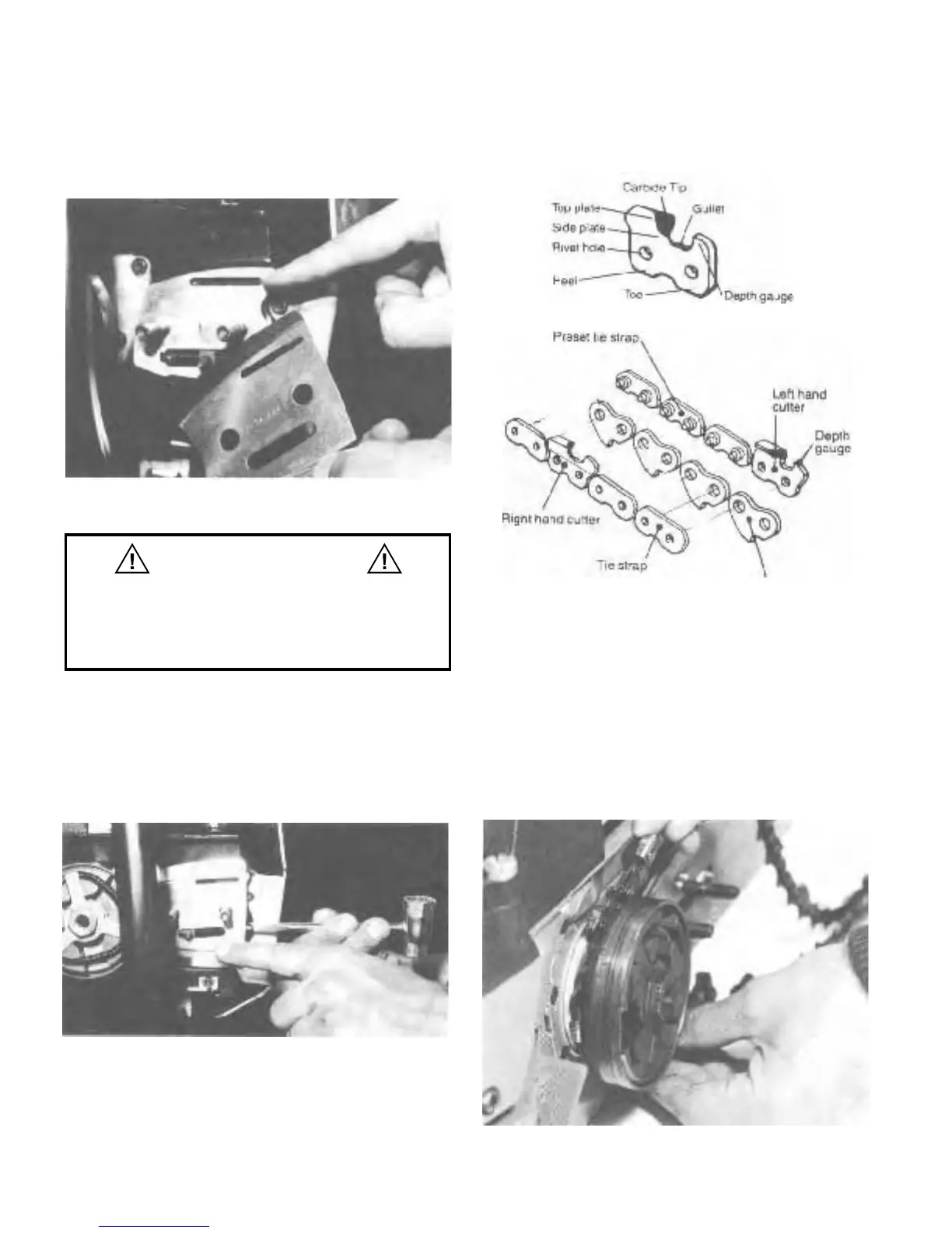
THE BAR PLATES
Now remove the outer bar plate. Note that the two bar
plates are similar (Fig. 5) but that the inner bar plate has an
additional slot that allows oil to reach the chain.
Fig. 5. Inner bar plate, with oil slot.
It is imperative that the inner
plate
with
the oil slot
is installed properly
or the
flow
of bar oil will
be
blocked and damage to the saw and chain, will
occur.
INSTALLING THE BAR AND CHAIN
Next, install the bar by first adjusting the chain tensioning
screw fully back (Fig. 6). This may have already been done
prior to shipping. Slide the bar into position, aligning the
chain tensioner with the adjusting hole in the bar.
Fig. 6. Chain tensioning screw.
THE CHAIN COMPONENTS
OPERATION & MAINTENANCE
/
9
Before installing the chain, take a moment to become fa-
miliar with the components of the chain (Fig. 7).
Fig. 7. Components of the chain
INSTALLATION OF THE CHAIN
Drive link
To install the chain, first align the chain so that the cutters
are pointing toward the tip of the bar as they lay on the top
of the bar. Slip the chain onto the clutch sprocket rim (Fig.
8). Then slip the chain into the grooves of the guide bar,
again verifying that the top cutters point toward the tip of
the bar.
Fig. 8. Insert the chain into the drive sprocket.
WARNING
 Loading...