4
MX Multi-Link Hand-held Programmer
The hand-held, sometimes called "Remote" programmer
ships with each MX system. This unit plugs into the
control module and provides user access to the program-
mable features.
Using The Programmer
There are five Screens accessible through the Remote:
Patch A
Patch B
Backup
Profile
Setup
1. Patch A Patch A* Dim.01
IN1:001 IN2.001
The function of this screen is to assign the DMX address
for each input. This can be done on a dimmer by dimmer
basis.
IN1 refers to the DMX1 board output.
IN2 refers to the DMX2 board output.
Dim. is followed by the dimmer number in the rack.
The "*" indicates the patch is active.
To Patch:
To activate Patch A: press Patch A twice.
To change Dimmer: press Dimmer up/ down.
To change values:
Look for the ":", this is the Active Input.
Type in the value using the Number Keys.
To switch editing to IN2: press IN2.
Note the ":" has moved to IN2.
To Clear Patch: press Clear twice.
To Set a one to one Patch: press Unity twice.
To assign patch by one number steps:
For IN1, and the dimmer number: press S1.
For IN2, and the dimmer number: press S2.
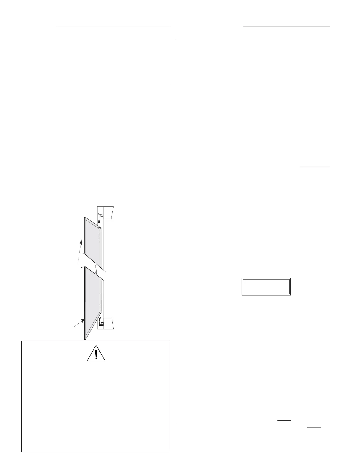
Removing / hanging the Door
The door is easily removed and re-hung. It may be useful
to remove the door for maintenance or service.
A key is required to operate the cam-style locks.
To remove the door, lift the entire door up so the lower hinge
pin is disengaged.
Angle the door out at the bottom and allow it to drop down
off the top hinge pin.
To replace the door, follow the reverse of the above
procedure.
Notice the top hinge pin is longer than the bottom, the
sequence noted above is the only easy way to hang or
remove the door.
Note: The door latches operate only with a key supplied
by EDI. If You need replacement keys, please
contact our Customer Service Dept.
Installation
For proper operation, the racks must be level, plumb and
square. If the rack is not level it will be difficult to install and
remove the dimmer modules.
Racks should be securely mounted to the floor and to the
wall if necessary. Holes are provided in the floor of the rack
for this purpose.
Lift top
in first
Then swing
bottom in
and let down
Operational Notes:
The modules are easily installed and removed without tools.
Since it is possible you have different types or rated
modules, we suggest the rack be closed and locked at all
times.
It is likely the modules are installed in a specific order to
correspond to the wiring of the rack. Keeping the door closed
and locked may prevent the modules being moved without
reference to this order.
The cooling efficiency of the rack may be seriously compro-
mised by the door being left open or removed, or by unfilled
dimmer slots. If this results in a dimmer(s) overheating, the
affected dimmer(s) will shut down and not operate until the
temperature has dropped to the operational temperature
range.
WARNING:
Maximum ambient operation and storage environ-
ment for this equipment is 104°F (40°C), with 90%
humidity, non-condensing.
Extreme caution is advised when liquids, food and
cigarettes are near any equipment.
During severe electrical storms, equipment should be
disconnected.
Failure to adhere to these requirements may result in
malfunction or serious damage.
 Loading...