Technical Bulletin # 970510 Page 2 of 7
Step 1: Module Placement & Verification
A. Move the Programming Slide Switch to the ‘on’ position (up). The System
Trouble LED will begin to flash and the Trouble Buzzer will sound at 20
ppm (pulses per minute).
B. Press the Reset Button. All the panel LEDs will turn on and then turn off.
After about 15 seconds the green power LED will begin a single phase
flash (flash and pause, flash and pause, etc.) the System Trouble LED
will turn a steady amber and the Zone Trouble LED’s will turn to a steady
amber.
C. At this point all Zone Trouble LED’s should be a steady amber, as well as
any Expansion Modules Enable/Disable LED.
Step 2: Initiating Device Circuit Programming
A. Press the Reset Button. The green power LED will begin a two phase flash
(flash-flash-pause, flash-flash-pause, etc.), the Zone 1 Trouble LED will
turn to steady red and the Circuit 1 and Circuit 2 Signal Trouble LED’s will
turn a steady amber.
note 1
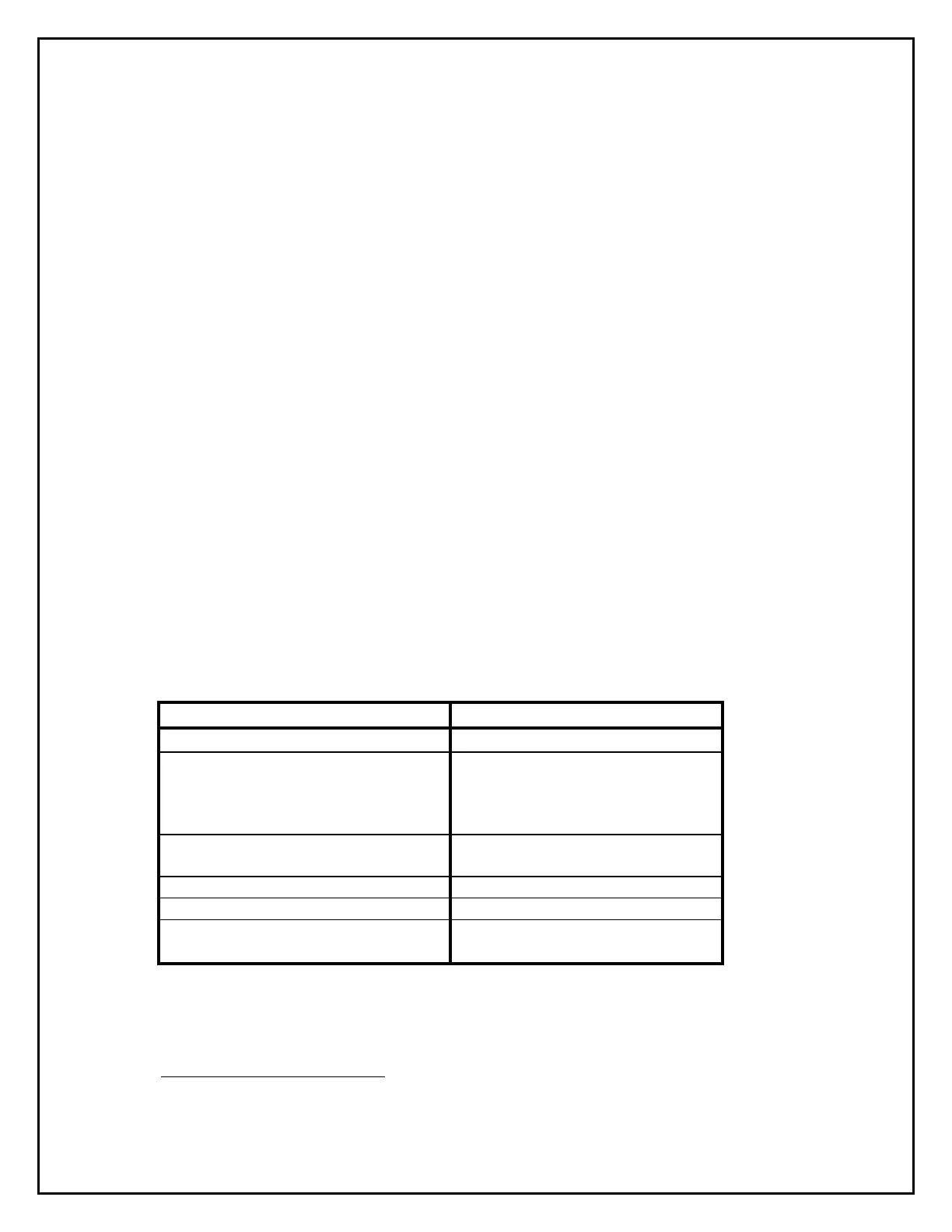
B. Use the Trouble Silence Button to step through the different zone types.
The different zone types as well as their Zone Trouble LED Color Codes
are listed in the following chart.
Initiating Device Circuit Zone Type Zone Enable/Disable LED Color Code
Alarm, NonVerified Detector Steady Red LED
Alarm, Verified Detector & Dry Contact
Alarm Initiating Devices (Do NOT use
this option. High Impedance Detectors
are not available)
Single Phase Flash Red (flash-pause,
flash-pause, etc.)
Alarm , Verified Detector ONLY For Low
Impedance devices only.
Two Phase Flash Red (flash-flash-
pause, flash-flash-pause, etc.)
Normally-Open Supervisory Steady Amber
Waterflow Steady Green
Waterflow with Retard Single Phase Flash Green (flash-
pause, flash-pause, etc.)
note 1
The Zone Trouble LED will be steady red unless it was previously programmed as a
different zone type.
 Loading...