2 / 4 P/N 270481 • REV 06 • REB 18JAN13
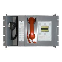
Figure 1: Chassis mounting diagram
Figure 2: Circuit board mounting diagram
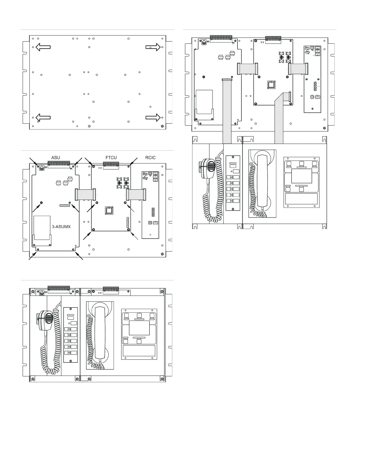
Figure 3: Installation complete
Figure 4: Cover installation
Wiring
Wire the 3-ASU/FT as shown in Figure 5, Figure 6, and
Figure 7.
Notes
• All wiring is supervised and power-limited.
• If a 3-RS485 card is not installed, connect AUDIO DATA
PRIMARY on the ASU card to AUDIO A OUT on the
3-CPUx card. See Figure 5.
If a 3-RS485 card is installed, connect AUDIO DATA
PRIMARY on the ASU card to AUDIO A IN on the 3-CPUx
card.
• Wiring from a 3-REMICA or 3-REMICP must be shielded
and enclosed in conduit. See Figure 5.
• All shields must be continuous and insulated from ground,
except at the originating panel.
• The REMOTE input is for MNEC applications only. Not for
supplemental use.
• Terminate Class B telephone risers with a 15 kΩ EOLR.
Do not install an end-of-line resistor if the riser is wired
Class A. See Figure 6.
 Loading...