P/N 3102000-ML • REV 1.0 • ISS 11APR12 3 / 10
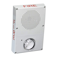
Figure 3: Jumper, switch, and protective cap locations
1
(6)
(3)
(5)
(2)
4
(1) Wire slot
(2) JP3 horn volume jumper
(3) Protective cap
(4) JP4 strobe pattern jumper
(5) JP1 horn pattern jumper.
(6) S2 candela-setting switch
Wiring
See Figure 4. Connect all wiring in accordance with national
electrical codes and applicable local requirements.
Caution: Equipment hazard. To avoid equipment damage,
ensure that the signal voltage does not exceed the voltage
rating of the device.
Figure 4: Wiring diagram
(4)
(5)
(6)
(1)
(2)
(3)
(1) Horn-strobe in −
(2) Horn-strobe in +
(3) Marking indicates the signal polarity
required to activate the device
(4) Horn-strobe out −
(5) Horn-strobe out +
(6) Not used
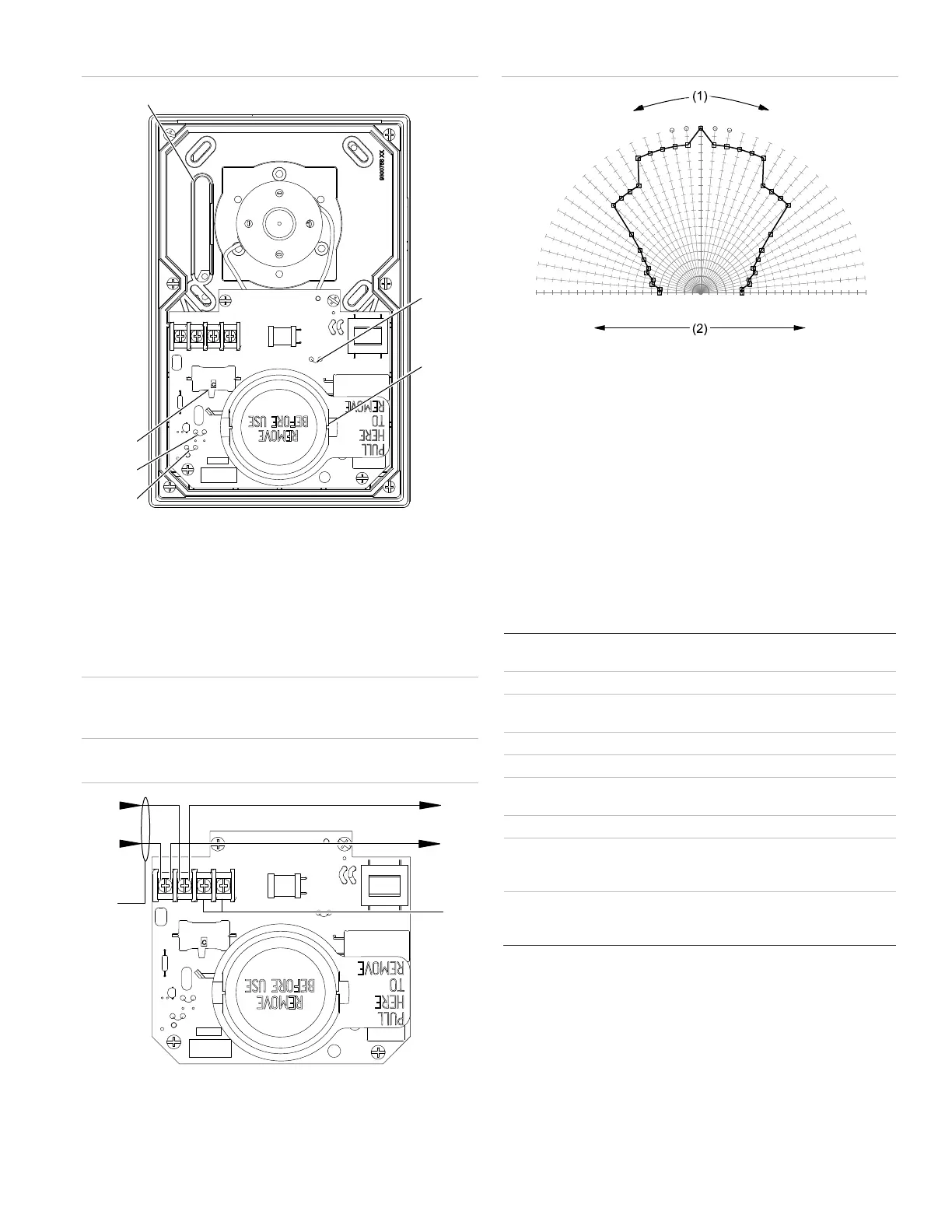
Figure 5: UL 1971 minimum light output (% of rating vs. angle)
100
95
90
85
80
75
70
65
60
55
50
45
40
35
30
25
20
15
10
5
0
5
10
15
20
25
30
35
40
45
50
55
60
65
70
75
80
85
90
95
100
0
5
10
15
20
25
30
35
40
45
50
55
60
65
70
75
80
85
90
-5
-10
-15
-20
-25
-30
-35
-40
-45
-50
-55
-60
-65
-70
-75
-80
-85
-90
(1) Angle
(2) Percentage of rated output
Note: Horizontal plot
Maintenance
Do not change the factory finish.
Perform a visual inspection and an operational test twice a
year, or as directed by the local authority having jurisdiction.
This unit is not serviceable or repairable. Should the unit fail to
operate, contact the supplier for replacement.
Specifications
Operating voltage
Horn-Strobe
24 VDC, 24 VFWR nominal
Dimensions (W × H × D) 5.6 × 8.5 × 1.4 in. (142 × 216 × 36 mm)
Sound level output See Table 4, Table 5, Table 6, and
Table 7
Horn tone 3.2 kHz
Strobe operating current See Table 11
Light output See Table 8, Table 9, Table 10, and
Figure 5
Wire size 12 to 18 AWG (0.75 to 2.50 mm²)
Compatible electrical box
Outdoor
Indoor
Model 449
4 in. square by 1.5 in. deep box
Operating environment
Temperature
Relative humidity
−40 to 151°F (−40 to 66°C)
0 to 95% noncondensing
 Loading...