2 / 2 P/N 3102062-EN • REV 002 • ISS 16NOV17
For Class A circuits, disconnect the Class A return wires. If
the SLC controller has a removable terminal block, simply
remove the block. The Class A return wires are not used.
3. Connect the USB cable to the SIGA-MFT, and then to
your PC.
4. Click Start > All Programs > Edwards Software >
SIGA-MFT Software to start the program.
During operation, the program may display a message
indicating that the external power supply is required. You can
plug in the external supply at any time during installation or
operation.
Refer to the SIGA-MFT Map Fault Tool User Guide
(P/N 3102035-EN) for instructions on using the tool to
troubleshoot the Signature SLC. A copy of the guide is
installed in the Edwards Software folder during installation of
the SIGA-MFT Software.
Wiring
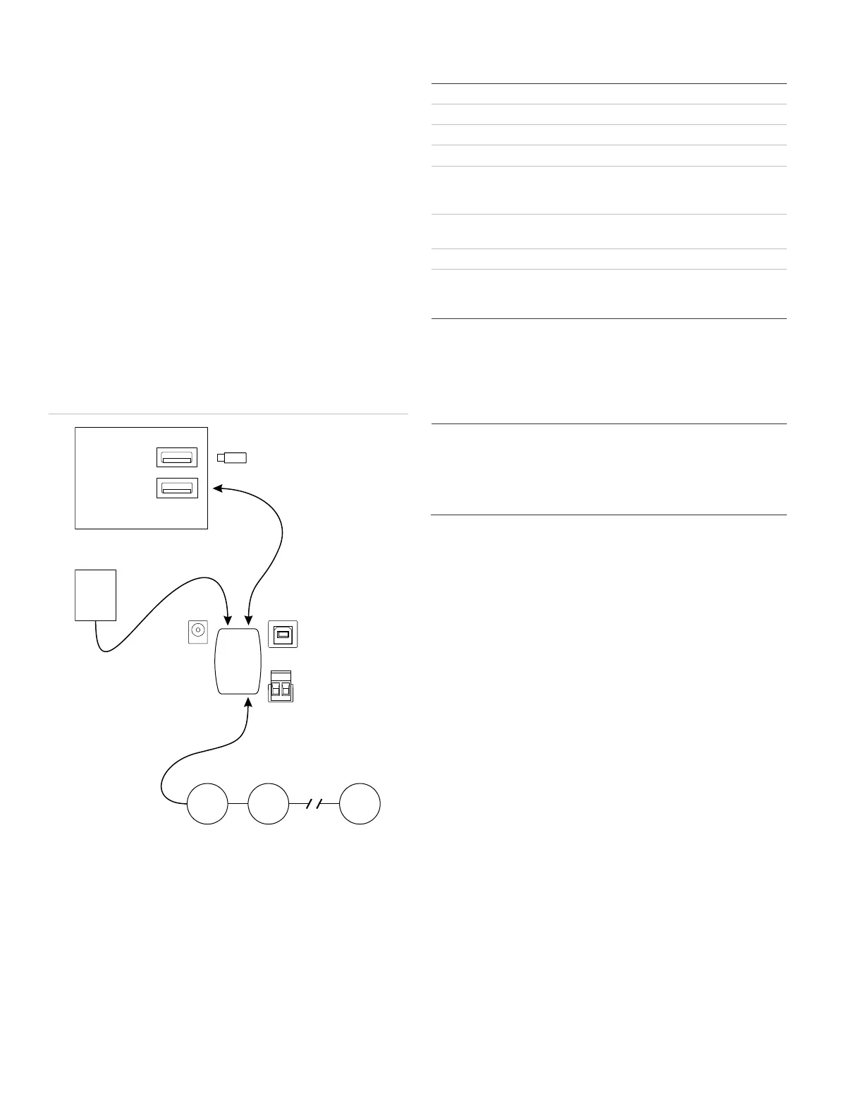
Figure 3: Connecting the SIGA-MFT
(1) USB flash drive with SIGA-MFT Software
(2) Field wiring from Signature SLC under test
(3) USB cable
(4) PC with SIGA-MFT Software installed
(5) 24 VDC external power supply (optional)
(6) SIGA-MFT
Maintenance
The SIGA-MFT does not require any periodic maintenance. If
needed, use a replacement fuse with the values shown in
“Specifications” below.
Specifications
External power supply
Voltage
Current
Positive center
2.1 mm ID × 5.5 mm OD × 9.5 mm (female)
Operating environment
Temperature
Relative humidity
32 to 120°F (0 to 49°C)
0 to 93% noncondensing
[1] When power is supplied by the USB port, the device operates on
5 VDC. The USB supply is limited to 500 mA by definition.
Regulatory information
This device complies with part 15 of the FCC
Rules. Operation is subject to the following two
conditions: (1) This device may not cause harmful
interference, and (2) this device must accept any
interference received, including interference that
may cause undesired operation.
Contact information
For contact information, see www.edwardsfiresafety.com.
 Loading...