Do you have a question about the Edwards SIGA-MFT and is the answer not in the manual?
Details the USB connection, external power jack, and diagnostic LEDs on the front face of the SIGA-MFT.
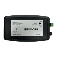
Identifies the fuse and SLC connection terminals located on the back of the SIGA-MFT device.
Describes the SIGA-MFT as a diagnostic tool for mapping faults, listing its accessories and diagnostic LED functions.
Instructs to install the SIGA-MFT Software from the USB flash drive before connecting the device.
Details connecting the SLC wiring to the SIGA-MFT, emphasizing disconnecting the SLC from the panel first.
Connects the SIGA-MFT to your PC using the USB cable after SLC wiring is completed.
Guide to launching the SIGA-MFT Software from the PC's Start menu after installation.
Lists voltage, current, fuse rating, wire size, and external power supply details for the SIGA-MFT.
Details the required PC operating system and the device's operating temperature and humidity limits.
States that the SIGA-MFT requires no periodic maintenance, but recommends fuse replacement if needed.
Outlines the conditions under which the device complies with FCC Rules regarding interference.
Provides the website address for obtaining contact information related to the SIGA-MFT or Edwards.
| Brand | Edwards |
|---|---|
| Model | SIGA-MFT |
| Category | Diagnostic Equipment |
| Language | English |