M
M
F
F
W
W
-
-
Z
Z
D
D
-
-
B
B
A
A
-
-
U
U
K
K
-
-
0
0
0
0
6
6
P
P
a
a
g
g
e
e
2
2
o
o
f
f
2
2
4
4
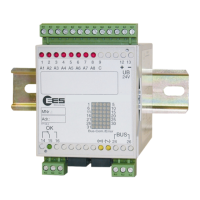
A system from the MFW product family
Table of contents
1 Applicability ....................................................................................................................................... 3
2 General notes......................................................................................................................................... 3
2.1 Symbols used .............................................................................................................................. 3
2.2 Terminology used ........................................................................................................................ 3
2.3 Safety instructions ....................................................................................................................... 4
2.4 Correct and proper usage ........................................................................................................... 5
3 Functional description ............................................................................................................................ 5
3.1 The MFW telecontrol family......................................................................................................... 5
3.2 2 wire line transmission medium .................................................................................................6
3.3 Inputs and outputs ....................................................................................................................... 6
3.3.1 Digital inputs......................................................................................................................... 6
3.3.2 Relay outputs ....................................................................................................................... 7
3.3.3 Analog inputs and outputs.................................................................................................... 8
3.4 Interfaces ..................................................................................................................................... 8
3.4.1 SDP interface ....................................................................................................................... 8
3.4.2 Protocol interface ................................................................................................................. 8
3.5 Connections and indicator lamps ................................................................................................ 9
4 Assembly and commissioning ........................................................................................................ 11
5. Configuration via DIP switch ........................................................................................................ 12
5.1 General principles...................................................................................................................... 12
5.2 Master module........................................................................................................................... 12
5.3 Substation module..................................................................................................................... 13
6 Parameterisation by PC.................................................................................................................. 14
6.1 Pulse width ................................................................................................................................ 14
6.2 Pulse output module.................................................................................................................. 14
6.3 Static binary inputs / saved statically.........................................................................................15
7 Diagnostic functions........................................................................................................................ 16
7.1 “Operating condition” indicator light and signalling relay. ......................................................... 16
7.2 Error codes ................................................................................................................................ 16
7.3 Station fault as a binary message ............................................................................................. 17
7.4 Diagnostics via interface............................................................................................................ 18
7.4.1 Master module terminal commands ................................................................................... 18
7.4.2 Substation module terminal commands............................................................................. 20
8 Technical data...................................................................................................................................... 21
8.1 Terminal assignments ............................................................................................................... 22
8.2 Dimensional drawings ............................................................................................................... 23
9 Accessories..................................................................................................................................... 24
© 2007
The copyright of these operating instructions belongs to the manufacturer. They contain technical data,
instructions and drawings for the function and handling of the devices and may not be reproduced in
part or in full or made accessible to third parties.