24
GB
considered improper and therefore a
source of risk to people and property.
PROTECTIVE CLOTHING
While working with the brushcutter,
always use safety protective approved
clothing. The use of protective clothing does
not eliminate injury risks, but reduces the injury
effects in case of accident. Consult your trusted
supplier to choose an adequate equipment.
The clothing must be proper and not an obstacle.
Wear adherent protective clothing. Protective
jackets and dungarees are ideal. Do not wear
clothes, scarfs, ties or bracelets that can stuck
into twigs. Tie up and protect long hair (example
with foulards, caps, helmets, etc.).
Safety shoes having skid-proof sole and anti-
piercing insert.
Wear protective goggles or face screens!
Use protections against noises; for example
noise reduction ear guards or earplugs. The
use of protections for the ear requests much
more attention and caution, because the
perception of danger audio signals (screamings,
alarms, etc.) is limited.
Wear gloves that permit the maximum
absorption of vibrations.
2. SYMBOLS AND SAFETY WARNINGS (Fig.21)
1 - Read operator’s instruction book before
operating this machine.
2 - Wear head, eye and ear protection.
3 - Wear strong boots and gloves when cutting
with metal or plastic blades.
4 - Be aware that objects can be thrown.
5 - Keep bystanders away 15 m.
6 - WARNING! – The surface can be hot!
7 - Warning! Kickback it’s danger.
8 - Purge Bulb.
9 - Type of machine: BRUSH CUTTER.
10 - Guaranteed sound power level.
11 - CE conformity marking.
12 - Serial number.
13 - Year of manufacture.
14 - Max. speed of output shaft, RPM
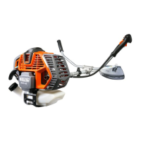
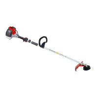
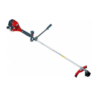
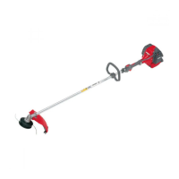
3. MAIN COMPONENTS (Fig.1)
1÷2 - Tools supplied
3 - Harness
4 - Bevel gear
5 - Curved guard
6 - Nylon line head
7 - Fuel tank cap
8 - Purge Bulb
9 - Carburettor adjustment screws
10 - Muer guard
11 - Spark plug
12 - Air lter
13 - Starter Handle
14 - Choke Lever
15 - Throttle trigger lockout
16 - STOP button
17 - Throttle lever
18 - Harness attachment
19 - Handle
20 - Shaft arm
21 - Button half-throttle
4. ASSEMBLY
FITTING THE SAFETY GUARD (Fig.4)
Fit the blade guard (A) to the shaft arm with screws
in a position allowing the operator to work safely (B).
NOTE: use the guard (C) only with nylon head.
Secure the guard (C) to the protection (A) by
means of the screw (D).
FITTING THE NYLON LINE HEAD (Fig. 6)
Put the upper (F) ange in place. Put the head xing
pin (H) in the appropriate hole (L) and tighten the
head (N) anti-clockwise by hand.
FITTING THE DISK (Fig. 7)
Fix the blade (R) onto the upper ange (F) making
sure that the rotation direction is correct.
Fix the lower ange (B), the cup (D) and tighten bolt
(A) anti-clockwise.
Put the pin provided in the appropriate hole (L)
to block the blade and allow the bolt (A) to be
tightened to 2.5 kgm (25 Nm).