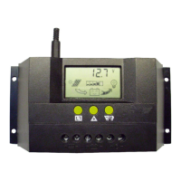
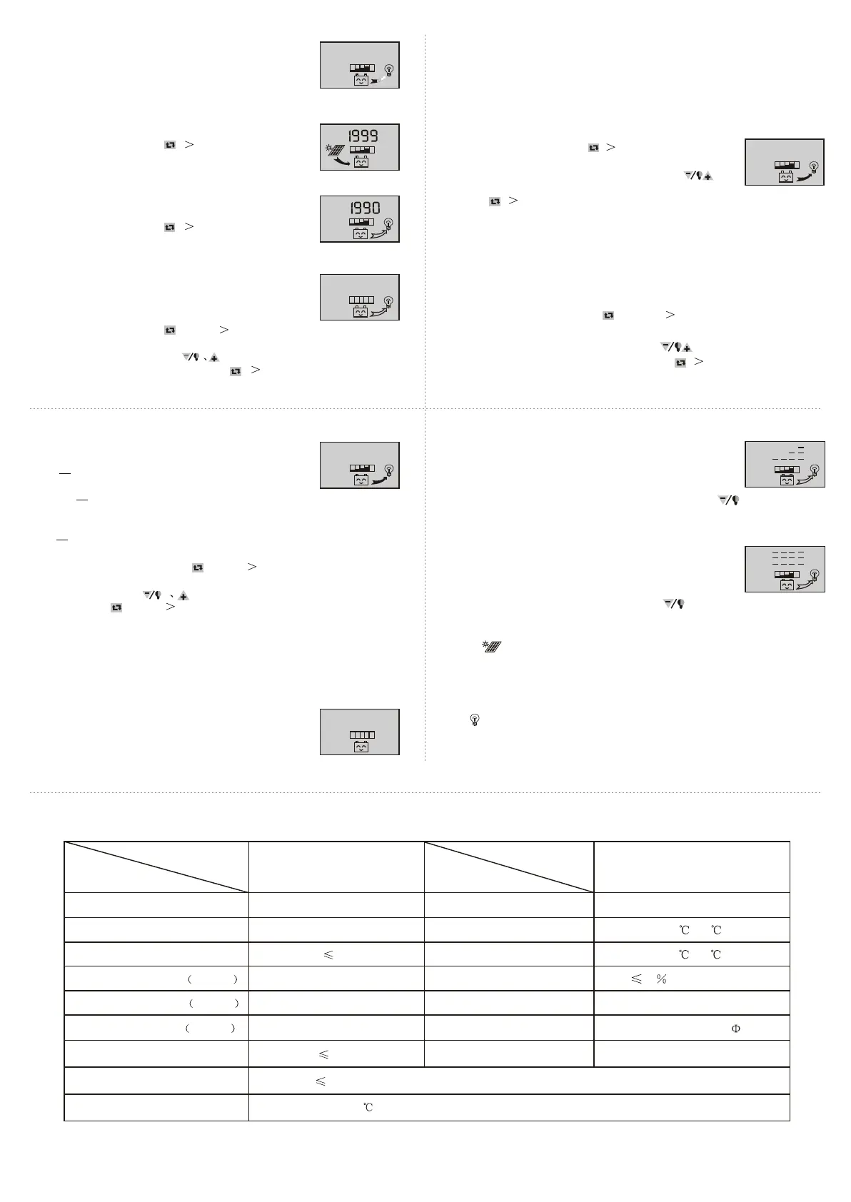
As shown as the right gure, the displaying number
is the load current.
3.5 The load current review
20.0
A
LO A D
As shown as the right gure, the displaying number is the
accumulating generating AH of solar panels
At this interface, press button ( 5 seconds), and it can
clear accumulative generating AH.
3.6 Review and clearing the accumulative generating AH of solar panels
Ah
P V
3.7 Review and clearing load accumulative discharging AH
As shown as the right gure, the displaying number is the
accumulative discharging AH of loads.
At this interface, press button ( 5 seconds), and it can
clear accumulative discharging AH.
Ah
LO A D
As shown as the right gure, the displaying number is the
protection voltage. And if the battery voltage is lower than
this voltage, the controller will disconnect the load loop to
prevent the battery from over-discharging.
At this interface, press button for long( 5 seconds),the
number starts to icker, and it means the controller enters into the interface of setting
the protection voltage. Use button to adjust this parameter.
After nishing setting, press button for long ( 5 seconds) to exit this interface
and the controller can store this setting number.
3.8 Review and setting low voltage protection function
V
LO A D
O F F
3.9 Review and setting recovering voltage for low voltage
condition
As shown as the right gure, the displaying number is the
recovery number. After the controller enters into low voltage
protection state, and when the battery voltage recovers to
be higher than the recovering voltage, then the controller
will reconnect the load loop automatically.
At this interface, press button ( 5 seconds),the number
starts to icker, and it means the controller enters into the
interface of setting the recovery voltage. Use button
to adjust this parameter. After nishing setting, press
button ( 5 seconds) to exit this interface and the controller can store this
setting number.
1 2.6
V
As shown as the right gure, the displaying number is the voltage of ceasing
charging. When the battery voltage reaches up to this voltage, the controller
will disconnect the charging loop to prevent the battery from o vercharging.
After the battery voltage drops, the controller will reconnect the charging loop.
At this interface, press button for long( 5 seconds),the number starts
to icker, and it means the controller enters into the interface of setting the
voltage ofceasing charging. Use button to adjust this parameter.
After nishing setting, press button for long ( 5 se conds) to exit this
interface and the controller can store this setting number.
3.10 Review and setting the voltage of ceasing charging
As shown as the right gure, it is the reviewing surface of the
load mode. Dierent numbers represent dierent load mode.
3.11 Review and setting the load mode
24
h
LO A D O N
24h indicating normal mode, loads are under the condition
of supplying power without breakdown;
1h~23h indicating delayed mode of light control, loads start
to supply power after dark and shun down after working for the delayed
setting hours
Oh indicating light control, loads start to supply power after dark and stop
working after dawn.
At this interface, press button for long( 5 seconds),the number starts to
icker, and it means the controller enters into the interface of setting the load
modes. Use button to adjust this parameter. After nishing setting,
press button for long( 5 seconds) to exit this interface and the controller
can store this setting number.
Breakdown & disposal
If the screen shows as the right gure, it means the battery
voltage is lower than the protection voltage. The controller
enters into the low voltage protection state and the load loop
disconnects. Use the solar panels or charger to charge for the
battery. When battery voltage recovers to the protection
voltage, the controller will recover to supply power for load,
and enter into the working state.
Low voltage protection & disposal:
V
If the screen shows as the right gure, and the light ickers, it
mean the current of the load loop is 1.2 times of the rated current
within 3 seconds, and the controller is at overloading state. After
removing some loads, the controller will supply power to the
loads automatically within seconds, or you can press button to recover the
power supply compulsively.
Overloading protection & disposal:
If the screen shows as the right gure, and the light ickers, it
means there happens short-circuit in the load loop, and the controller
is at short-circuit protection state. Please check whether the loads
are damaged and whether the connecting cables are short-circuit.
After eliminating the breakdown, press button to recover the power supply
for the loads.
Short-circuit protection & disposal:
Breakdown & disposal of solar panels:
Sign ickering means the controller do not detect the existence of solar panels.
Please check whether the connecting with the solar panels is in good condition, and
check whether the cables connecting the solar panels and the controller are i n
open-circuit condition.
If
ickers when you turn on the load, it means the starting impulsion current is
more than twice of the rated working current. Please restart the controller for times.
Other exceptional conditions: Please contact the distributor or manufacturer.
Load impulsion breakdown:
model
parameter
rated working voltage
rated working current
voltage of solar panels
oat charging voltage settable
low voltage protection settable
low voltage recovery settable
no load loss
loop voltage drop
temperature compensation
SOLAR30
12V/24V
30A
48V
13.8V/27.6V
10.7V/21.4V
12.5V/25.0V
30mA
170mV
-4mV/Cell/
model
parameter
installable maximum cable
working temperature
storage temperature
temperature requirement
dimension
distance of installation holes
weight
7# AWG (16mm )
2
-10 ~60
-30 ~70
90 ,no condensation
90 mmx188 mmx48 mm
60 mmx178 mm -- 5
360g
Product Parameter
1 0.7
10.6
SOLAR30
7 8
9 10
11
 Loading...