Do you have a question about the EFORT ER20-1100 and is the answer not in the manual?
Guidance on essential safety practices before installing, operating, or maintaining the robot.
Measures to prevent accidents, including robot design, safety structures, and operational precautions.
Standardized gestures for controlling the industrial robot safely during operation and communication.
Explanation of safety labels affixed to the robot body to warn users of potential hazards.
Procedures and requirements for transferring robot ownership, including documentation and compliance.
Guidelines for the safe and proper disposal of robots and their components, including battery handling.
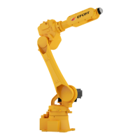
Overview of the main components of an industrial robot, including body, control cabinet, and teach pendant.
Instructions for verifying the integrity and completeness of the robot package upon delivery.
Information displayed on the robot's nameplate, such as model, weight, voltage, and manufacturing details.
Identification of robot body parts and direction indicators for each axis of movement.
Definition of operational range limits and home positions for each robot axis to ensure safety.
Key performance specifications of the robot, including speed, motion range, payload, and repeatability.
Guidance on the maximum payload capacity of the robot wrist, considering weight, torque, and inertia.
Specifies the maximum weight the robot arm can carry at the wrist.
Details the maximum static torque the robot wrist can handle for each axis.
Defines the maximum allowable moment of inertia for payloads attached to the robot wrist.
Visual representation of allowable payload limits based on wrist axis torque.
Procedures and precautions for safely transporting the industrial robot and its control devices.
Essential safety guidelines for handling and moving the robot and control equipment during transport.
Description of necessary tools and fixtures for securely handling and fixing the robot during transport.
Detailed methods for handling and transporting the robot using lifting belts or forklifts, including specific gestures.
Guidelines and safety measures for installing the industrial robot in its operational environment.
Requirements for establishing safety protection space and implementing safety guards around the robot.
Instructions for properly fixing the robot base to the foundation, ensuring flatness and stability.
Specifications for concrete foundation, bearing capacity, and chemical bolts required for ground installation.
Procedures for installing the robot using brackets, ensuring connection strength and safety.
Precautions for upside down and wall-mounted robot installation, including fall protection.
Parameters for the robot's working, transportation, and storage environment, including temperature and humidity.
Details of external interfaces for robot integration, including end load mounting and peripheral dimensions.
Dimensions and specifications for the end load mounting flange used for attaching tools or end effectors.
Dimensional diagrams for peripheral installation, showing mounting points and clearances.
Table defining the signal connections for the M12 terminal on the robot's forearm.
Schematic of pneumatic channels and signal interfaces, including air pipe diameter and pressure specifications.
Scheduled maintenance tasks to ensure the robot's optimal performance and longevity.
Daily checks focusing on noise, vibration, ventilation, wiring, and leaks.
Quarterly checks for teach pendant, ventilation, cables, components, and screw tightening.
Annual maintenance tasks including component inspection and external screw tightening.
Periodic checks every three years, focusing on lubricant replacement in reducers and wrist parts.
Inspection and maintenance procedures for critical bolts used in robot installation and component assembly.
Guidelines for replacing robot lubricant based on operating hours or time intervals, including capacity and azimuth.
Table detailing the required capacity and type of lubricant for different robot axes and components.
Recommended axis positions for efficient and safe lubricant replacement or supplement.
Step-by-step instructions for replacing lubricant in specific robot axes, emphasizing proper technique and safety.
Procedure for safely releasing residual pressure in lubricant cavities after injection, with motion guidelines.
Procedures for maintaining timing belts, including checking for wear, loosening, and replacement.
Instructions for adjusting and tightening timing belts using a tensioner to maintain precision.
Guidance on when and how to replace timing belts, including checking for damage and required tools.
Requirements for the robot's maintenance area, including safety fencing and access control.
Safety measures for the working area, such as safety fences, doors, interlocks, and height restrictions.
Qualifications and safety training required for personnel performing robot maintenance and operations.
Process for calibrating the robot's home position, relating axis azimuths to encoder values.
Methods for software and hardware calibration of the robot's home position, often requiring expert assistance.
Steps for mechanically calibrating each robot axis's home position by aligning marks and recording coordinates.
Procedure for replacing encoder batteries that save home position data, including safety precautions.
Diagnosis and troubleshooting for common vibration and abnormal noise issues in the robot body.
Troubleshooting steps for abnormal noise occurring after shutdown or grease replacement.
Addressing vibration and noise caused by cabling, signal issues, or external electromagnetic interference.
Identifying and rectifying causes of robot body shaking, such as loose screws or internal component damage.
Diagnosing and resolving motor overheating issues due to environmental factors or improper operation.
Troubleshooting for robot joints that fail to lock, leading to arm dropping due to gravity.
Identifying and resolving causes of oil leakage from robot joints, including seal failures and loose screws.
Addressing issues where the robot's repositioning accuracy exceeds allowable limits.
Troubleshooting position deviation caused by unstable peripheral device connections or interference.
Resolving position deviation issues resulting from parameter modifications or loss of home position data.
Diagnosing and rectifying teach pendant alarms related to motor encoder wiring or disconnection.
Reference table for tightening torques of various screw sizes for different materials.
List of recommended spare parts, including servo motors, gears, seals, and consumables.
| Payload | 20 kg |
|---|---|
| Reach | 1100 mm |
| Number of axes | 6 |
| Repeatability | ±0.05 mm |
| Installation | Floor |