Mount the Buzzer
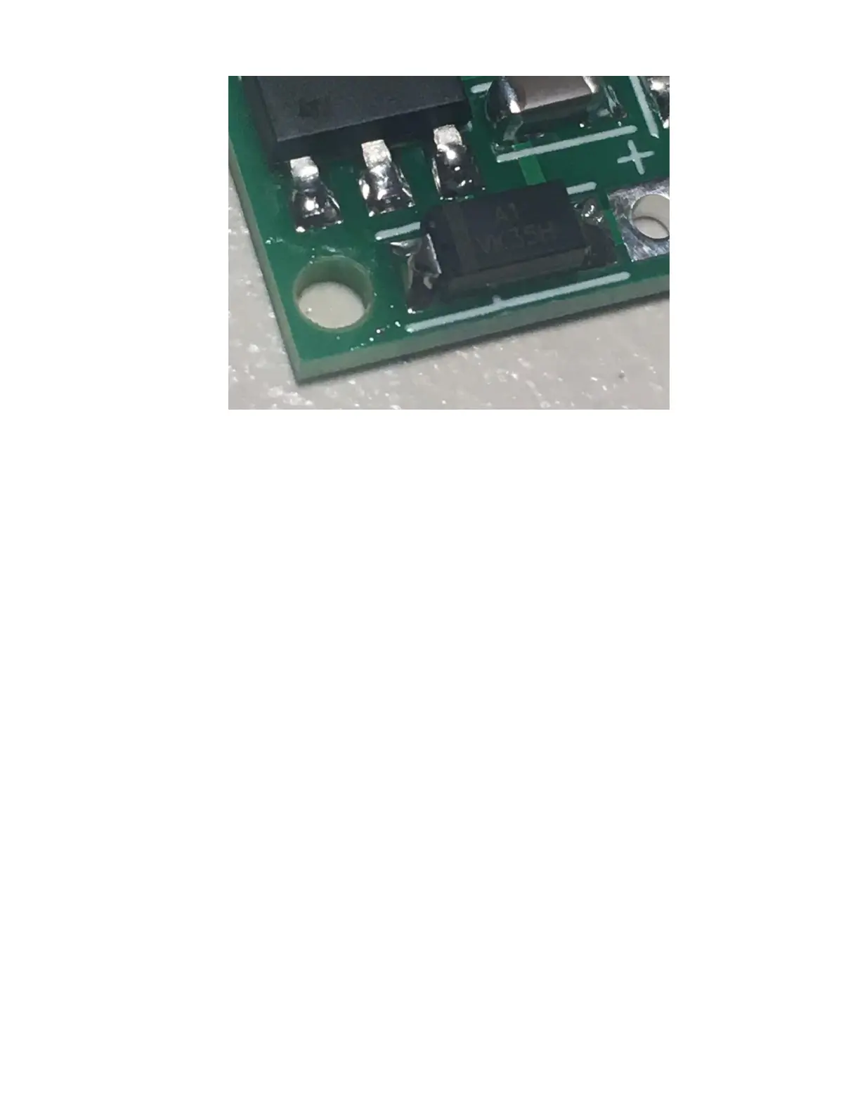
___ Locate the spot for the buzzer, there are two holes: one just to the left of the processor,
and one just below the 10K/103 resistor. The one next to the 10K resistor has a “+” marking
next to it.
___ When you mount the buzzer it will cover a few of the parts, so you need to check the
solder joints on a few of them right now with a 10x jeweler’s loupe, and touch them up if
necessary. Once you solder the buzzer, you will not be able to get to them, and you don’t
want to have to remove the buzzer… it’s not all that easy.
___ With a 10x jeweler’s loupe, check the solder joints on:
___ The 10K/103 resistor
___ The .1 uF capacitor to the left of the processor
___ The 10 uF capacitor to the left of the .1 uF capacitor
___ The .1 uF capacitor above the baro sensor
___ The processor
___ When you’re satisfied that those solder joints are good, place the buzzer in the two
mounting holes. Note that the buzzer has a “+” marked on one side, and that the lead next to
the “+” side is longer than the other lead. That lead must be mounted in the bottom hole on
the PC board with the “+” mark next to it.
___ With a piece of masking tape, hold the buzzer in place.
 Loading...