3
5
3
12
4
6
7
8
9
11
13
16
15
14
12
10
11
Wiring diagram
22
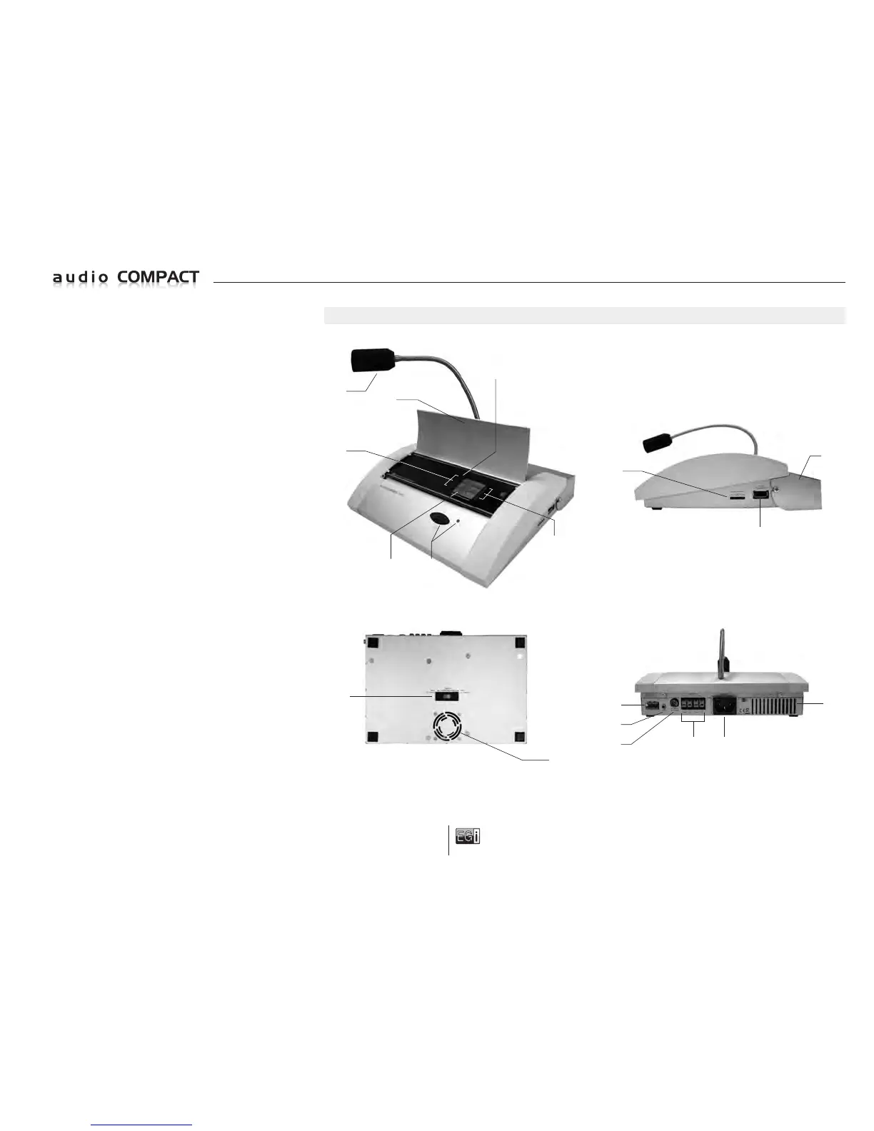
ELEMENTS
10401 - Auto-amplified console
ELEMENTS
1 Call button and message pilot light.
If the Led blinks this indicates that there is mains power.
A steady Led light indicates that a message is being broadcast
via the microphone.
2 Graphic LCD display.
3 Menu access keys.
4 Front protection cover.
Press PUSH to open or close the cover.
5 ON/Stand-by button.
6 Electret unidirectional microphone.
7 Micro SD memory card input for DIN-DON and
pre-recorded messages.
8 USB memory input to play MP3 music.
9 Cabling protection cover.
10 Voltage selector 110 V~ / 230 V~.
11 Electric fan and ventilation grille.
12 230V~ or 115 V~, input connection plug.
13 Audio output for Zone 1 and Zone 2 speakers (2 x 50 W).
14 RF FM antenna jack.
15 Auxiliary audio jack input 3.5 mm. ST.
16 MILLENNIUM output for Zone 3.
 Loading...