EasyManua.ls Logo

Eichhorn 100001844 User Manual

Eichhorn 100001844
2 pages
To Next Page IconTo Next Page
Page #1 background imageLoading...
Page #1 background image
www.eichhorn-toys.de
6
7
10 000 1844
4/4
Simba Toys GmbH & Co. KG · Werkstr. 1 · 90765 Fürth · Germany
eichhorn-toys.de | service.eichhorn-toys.de Simba Toys UK Ltd., Broomfield House, Bolling
Road, Bradford BD4 7BG • Fabriqué en Chine / Hergestellt in China / Made in China / Fabricado en
China / Fabricado na China / Fabbricato in Cina 66661122
D: Aufbauanleitung
GB: Instructions for assembly
F: Instructions de montage
I: Istruzioni di montaggio
NL: Montagehandleiding
E: Instrucciones de montaje
P: Instruções de montagem
DK: Monteringsvejledning
S: Konstruktionsanvisning
FIN: Kokoamisohje
N: Veiledning for oppbygging
H: Felépítési utasítás
CZ: Návod pro sestavení
PL: Instrukcja montażu
GR: Οδηγίες συναρμολόγησης
TR: Kurulum kılavuzu
SI: Navodilo za postavitev
HRV: Uputa za sastavljanje
SK: Návod na montáž
BG: Инструкция за монтаж
RO: Instrucțiuni de montaj
UA: Вказівки зі встановлення
EST: Paigaldusjuhend
LT: Montažo instrukcija
LV: Uzstādīšanas pamācība
AR:
   
Question and Answer IconNeed help?

Do you have a question about the Eichhorn 100001844 and is the answer not in the manual?

Eichhorn 100001844 Specifications

General IconGeneral
BrandEichhorn
Model100001844
CategoryToy
LanguageEnglish

Summary

Eichhorn Workbench Assembly

Parts Identification

Lists and identifies all components required for assembly, including screws, wooden pieces, and accessories.

Step 1: Base Assembly

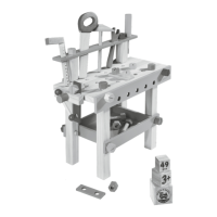
Instruction for the initial assembly of the workbench base structure, connecting the main frame components.

Step 2: Attaching Workbench Surface

Guidance on connecting the primary workbench surface to the assembled base structure.

Step 3: Installing Support Beams

Instructions for adding vertical support beams and horizontal bracing for the workbench.

Step 4: Securing Back Panel

Details on attaching the back panel or support elements to the workbench structure.

Step 5: Assembling Vice Mechanism

Instructions for assembling and attaching the functional vice component to the workbench.

Step 6: Further Assembly Details

Illustrates additional steps in the assembly process, showing specific component placements.

Step 7: Final Assembly Configuration

Depicts the final stages or specific configurations for completing the workbench assembly.