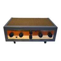
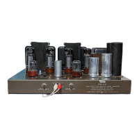
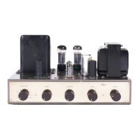
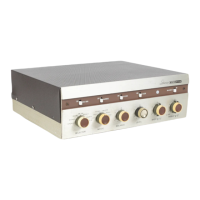
1. (\)Fig.
9. Connecta21/2"
pieceofgreenwirefromR24-
5(Sl)toXV4-
7(Sl).
2. (1) /
Fig. 9.
Connect a 9" piece of black wire from XV5-8 (C) to T84
(C).
3. ( ) Fig.
9. Connect a 9" piece of black wire from XV6-
8 (C) to TB3-
1 (C).
4.
(vi
Fig. 9. Cut
all leads on two
47mmf, 10% disc capacitors, C31 and
C32, to 3/4"
. Connect C32 from TB2-
4 (C) to TB3-1 (C) and the other capaci-
tot, C31,
from 1Bl-4 (C) to 184 (C). Each lead is to be covered with a
1/2"
piece of spaghetti.
5. h)Fig.
9. Connect a 1" piece of
bare wire from TBl-
l (S2) to TB3-
2 (S1).
6. ( )
/ Fig. 9. Connect a I" piece of bare
wire frQm TB2-
1 (S2) to ground
lug II
H;' (Sl).
7. (\
/,
Fi.g. 9. Cut all leads on the two 22KO (red, red
, orange, gold) 5%
resistors, R58 and
R59, to 3/4". Connect R58 from TB2-
4 (S3) to TB3-
1 (S3)
and R59 from 1B 1-
4 (S3) to 184 (S3). Each lead is to be covered with a
1/2"
piece qf spaghetti.
8.
(\;1 Fig. 9.
Cut all leads. on the six
10KQ (brown, black, orange, silver)
... res istors, R40, R41,
R52; R53, R54, and R55, to 1/2"
. Connect R55 from
XV8-6
-0 (S.
2) to XV8-
2(Sl). Conne~t R53
resistor from XV7-8(C)toXV7-
2 (Sl). Con-
nect R54 from XV10-
8 (S2) to XV1Q;..
2 (S 1)
Connect R52 from XV9-
8 (C) to
XV9-2 (S 1).
Connect R41 from TB9-
1 (C) to 1B9-
2 (C). Connect R40 from
TB18-
1 (C) to TB18-
2 (C).
9. ~./) ~ig. 9..
Connect a 3" piece of grey wire from TB20-
2 (C) toXV9-
8 (S2).
10; (fI) Fig. 9. Cut all
leads on the two 330KO (orange, orange, yellow, silver)
resistors, R48 and
R50 to 1/2"
. Connect R50
from TB 19-2 (C) to TB 19-
1 (C).
Connect R~8 from TB20-
1 (C) to TB20-
2 (C).
11. (t)lFig. 9. Cutall leads on the two 330KO(orange,
orange, yellow; silver)
resistors, R49 and
R51 to 3/4"
. Connect
R49 from TB 10-
1 (C) to XV7-8 (C).
Connect R51 from XV7-
6 (C) to ground lug
" I" (C).
12. (\;
Fig. 9.
Cut all leads on the four.
025mfd (25K or 25,
OOOmmf) disc
capacitors, C33, C34,
C35, and C36, to 3/4"
. Connect C33
from XV5-
1 (C)
to XV7-
8 (S3). Connect C35 from XV5-
3 (C) to XV7-
6 (S3). Connect
C34
from XY6-1 (C) to TB20-
2 (S3). Connect
C36 from XV6-
3(C) to TB19-1 (S3).
13.
Fig 9. Cut
all leads on the two
100KO (brown, black, yellow)' gold)
5% resistors,
R45 and R46, to 1/2"
. Connect
R45 from XV5-
1 (C) to TBI0-
(S2). Connect R46 from XV6-
3 (C) toTB19-
2 (C).
14. (
Fig. 9. Cut all
leads on the two 100KO (brown, black, yellow, gold)
5% resistors,
R44 and R47" to 3/4"
. Connect R47 from XV5-
3 (C) to ground
lug "
1" (C).
Connect R44 from XV6-
1(C) to TB9-
2 (C).
15.
,or)
Fig. 9.
Cut all leads on
the two 225mmf disc capacitors, C25 and
C28 to 3/4"
. Connect C25
from XV5-
1 (S3) to TBI0-
l (S3).
Connect C28
from XV6-
3 (S3) to TB 19-
2 (S3).
16. (\#
) Fig. 9. Cut
all leads on the
two 225mmf disc capacitors, C26 and
C27, to 1"
. Connect
C27 from XV5-
3 (S3) to ground lug
" I" (53). Connect
C26 from XV6-
1 (53) to TB20- 1 (S2).
17. (\')'j:ig.
9. Cut all leads on two 1.
8KO (brown, grey, red, gold) 5% resis-
tors, R42 and R43, to 3/4"
. Connect R43 fromXV5-
8(S2) to TB7-
1 (S5).
Con-
nect R42ifrom XV6-8 (S2) to TB21-
1 (C).
18.
~j
Fig. 9. Cut
all '
leads on two 470KO (yellow, violet, yellow, silver)
resistors, R38 and
R39, to 3/4"
. Connect R39 from
XV5-6(C) to TB9-
2 (S5).
Connect R38 from XV6-
6 (C) to TB18-
2 (S5).
19.
(,,~ Fig. 9. Cut all leads on
two 150mmf disc capacitors, C23and C24, .
to 1"
. Connect C23 from XV5-
6 (C) to TB9-
1 (S2). Connect C24 from XV6-
(C) to TB 18-1 (S2).
20. (')'Fig.
9. Connectal1/4"
pieceofbarewirefromTB7-
2(C)toS5-
1(S1).
21. (\) Fig.
9. Connect a 3/4" piece of bare wire
from TB21-
2 (C) to XV6-
7(Sl).
22. (,.
1 Fig. 9. Connect a pI pieceofbarewirefromXV5-
2 (Sl) to XV5-
6 (S3).
23. ,
("J Fig. 9. Cut a
1/1 piece
of bare wire from XV6-
2(S1) to XV6-
6 (S3).
24. (\
/~i9' 9. Cut
all leads on four. 1 mfd (brown,
black, yellow, yellow)
molded capacitors, C17
C18,
C21 and C22, to 3/4"
. Cover each lead
with a
1/2" piece of
spaghetti. Connect
C17 from XV3-9 (C) to TB8-
1 (S2). Con-
nectC18
from XV4-
6(C) to TBl1-
2(S2). Connect C21
from XV3-
1 (C)to
TB7-2 (S4). Connect C22 from XV4-
1 (C) to TB21-
2 (C).
Dress the leads as
shown and push all capacitors
flat against the chassis.
 Loading...