VOLTAGE
AND
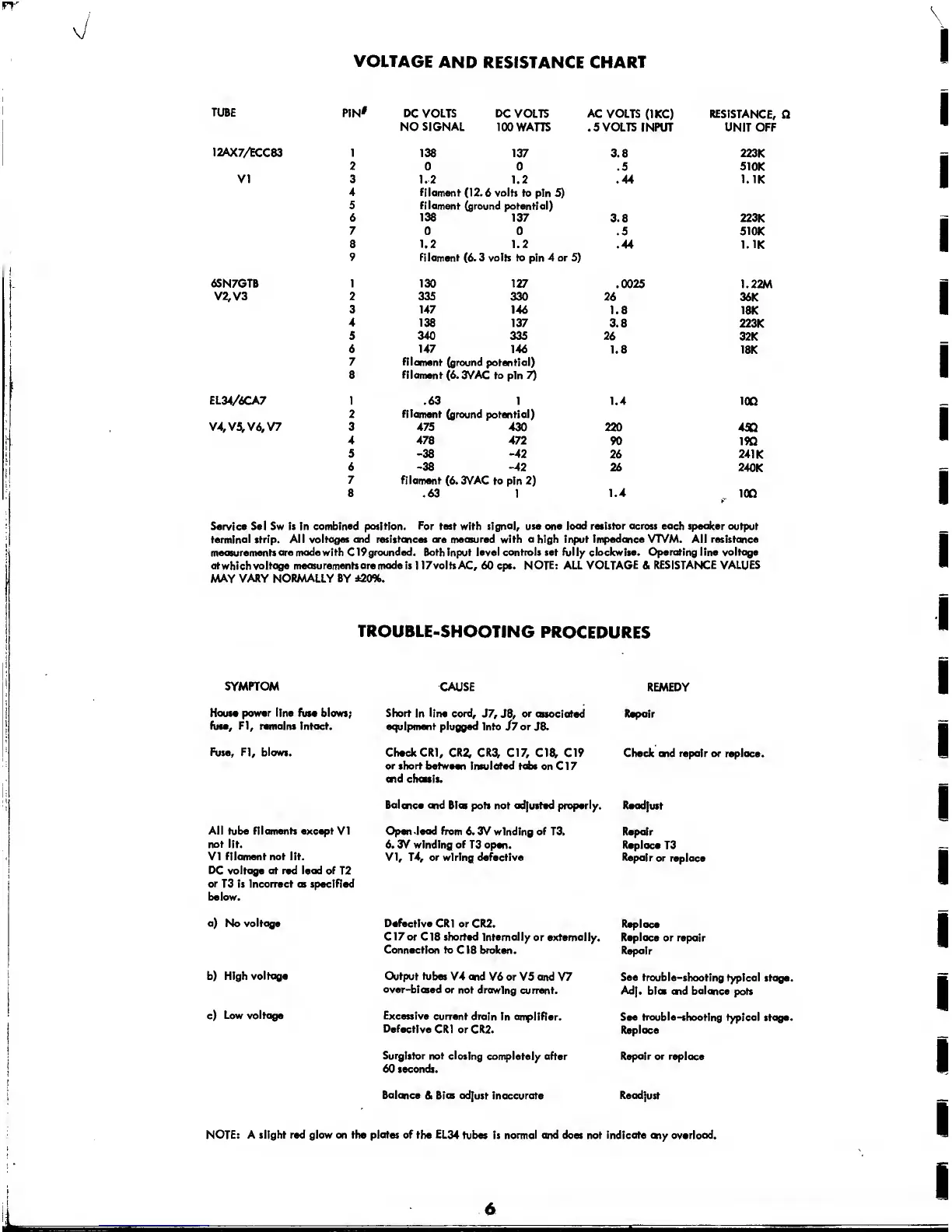
RESISTANCE CHART
TUBE
PIN'
DC VOLTS DC
VOLTS
AC
VOLTS
(1KC) RESISTANCE,
NO
SIGNAL
100 WATTS
.5 VOLTS INPUT
UNIT OFF
12AX7/ECC83 1
138 137
3.8 223K
2
0 0
.5
51
OK
Vi 3
1.2 1.2 .44
1. IK
4 filament
(12.6 volts to
pin
5)
5
filament
(ground potential)
6
138
137
3.8
223K
7
0 0
.5 510K
8 1.2 1.2
.44 1. IK
9 filament
(6.
3 volts to pin 4 or
5)
6SN7GTB 1 130 127
.0025
1.22M
V2,V3 2 335
330 26
36K
3 147
146
1.8
18K
4 138
137
3.8
223K
5
340
335 26
32K
6
147
146
1.8
18K
7 filament
(ground potential)
8 filament
(6.
3VAC to
pin
7)
EL34/6CA7 1
.63 1 1.4
ion
2
filament
(ground potential)
V4,V5, V6, V7 3 475 430
220
45Q
4
478
472
90 190
5
-38 -42
26
241
K
6
-38
-42
26
240K
7
filament
(6.
3VAC
to pin
2)
8
.63 1
1.4
*
100
Service Sei Sw is in
combined position. For test with signal, use one
load
resistor
across each
speaker output
terminal strip.
All voltages and resistances are measured with a high input impedance VTVM. All resistance
measurements
are madewith C19grounded. Both input level controls set fully clockwise. Operating line voltage
at which voltage
measurements are made
is
1 17voltsAC,
60 cps.
NOTE: ALL VOLTAGE
&
RESISTANCE VALUES
MAY
VARY NORMALLY BY ±20%.
TROUBLE-SHOOTING
PROCEDURES
SYMPTOM
CAUSE REMEDY
House
power line fuse
blows;
fuse, FI,
remains
Intact.
Short
In
line cord,
J7, J8, or associated
equipment plugged
Into
J7
or J8.
Repair
Fuse,
FI,
blows.
Check CR1,
CR2,
CR3,
C17, C18, C19
or short between insulated tabs on
Cl
7
end chassis.
Check and repair or replace.
Balance end Bias
pots not ad|usted properly. Readjust
All
tube
filaments
except VI
not
lit.
VI filament
not lit.
DC voltage at red lead of
T2
or T3
is Incorrect as specified
below.
Open
lead
from 6.
3V winding
of
T3.
6. 3V
winding
of
T3 open.
VI, T4,
or wiring defective
Repair
Replace
T3
Repair
or
replace
a)
No
voltage
Defective
CR1 or CR2.
C17 or C18 shorted Internally
or externally.
Connection to
C18 broken.
Replace
Replace
or repair
Repair
b) High
voltage
Output tubes
V4 end
V6 or V5 and
V7
over-biased or
not drawing
current.
See trouble-shooting
typical stage.
Adj.
bios
end balance
pots
c)
Low voltage
Excessive
current drain
In
amplifier.
Defective
CR1 or CR2.
See
trouble-shooting
typical stage.
Replace
Surgistor
not
closing completely after
60 seconds.
Repair or replace
Balance
&
Bias adjust
inaccurate
Readjust
NOTE: A slight red glow on the plates of the EL34
tubes is
normal and
does not
Indicate
<*iy overload.
6
 Loading...