MX99
PAGE 5
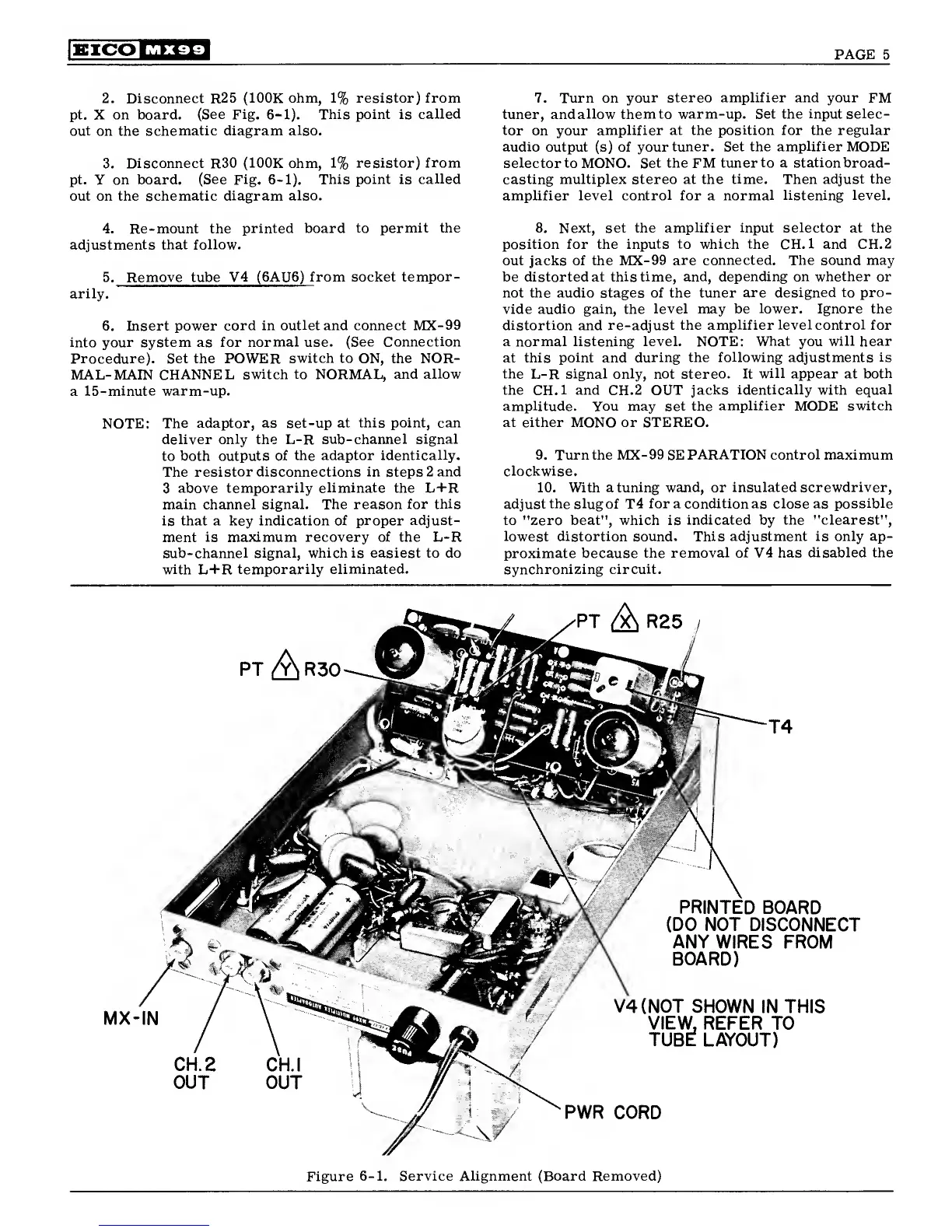
2. Disconnect
R25
(100K
ohm, 1
%
resistor) from
pt.
X
on board.
(See Fig. 6-1). This point is
called
out
on the
schematic diagram also.
3.
Disconnect
R30
(100K ohm,
1
%
resistor) from
pt.
Y
on board.
(See
Fig. 6-1).
This point is
called
out on the schematic
diagram also.
4. Re-mount the
printed board
to permit the
adjustments that follow.
5. Remove tube V4 (6AU6)
f rom socket
tempor-
arily.
6. Insert power
cord in
outlet
and connect MX-99
into your system as for
normal
use.
(See Connection
Procedure). Set the POWER
switch to
ON,
the NOR-
MAL-MAIN CHANNEL
switch
to
NORMAL,
and
allow
a
15-minute warm-up.
NOTE:
The adaptor, as set-up
at this point, can
deliver
only
the L-R
sub-channel
signal
to both outputs of
the adaptor
identically.
The
resistor disconnections in steps
2 and
3
above
temporarily eliminate the L+R
main
channel signal. The reason for
this
is
that a key
indication of proper adjust-
ment
is maximum recovery of the L-R
sub-channel
signal, which
is
easiest to do
with L+R
temporarily eliminated.
7. Turn on
your stereo amplifier and your
FM
tuner,
andallow themto warm-up. Set the
input
selec-
tor
on your
amplifier at the position for the
regular
audio
output (s) of your
tuner. Set the
amplifier
MODE
selector to
MONO. Set
the FM tuner
to
a
station
broad-
casting multiplex stereo at the
time.
Then
adjust the
amplifier level
control
for a
normal listening level.
8.
Next, set the
amplifier input selector
at
the
position for the
inputs to which the
CH.
1
and CH.2
out jacks of the MX-99
are connected. The sound may
be distorted at this
time, and, depending on whether or
not the audio stages of the tuner
are designed to pro-
vide audio
gain,
the
level may be
lower.
Ignore the
distortion
and
re-adjust the
amplifier level control
for
a normal listening
level.
NOTE:
What
you
will hear
at this
point
and
during the
following
adjustments
is
the
L-R
signal only, not stereo. It
will
appear at
both
the CH.l and
CH.2
OUT
jacks identically with equal
amplitude. You may set
the amplifier
MODE
switch
at
either
MONO or STEREO.
9.
Turn the MX-99 SEPARATION
control
maximum
clockwise.
10. With a
tuning
wand, or
insulated screwdriver,
adjust the
slug of T4 for a condition as
close
as
possible
to
"zero
beat", which
is
indicated
by
the "clearest",
lowest distortion sound. This
adjustment is only ap-
proximate because
the removal
of V4
has
disabled the
synchronizing circuit.
CH.2
OUT OUT
BOARD
(DO NOT
DISCONNECT
ANY WIRES FROM
BOARD)
V4(N0T
SHOWN IN THIS
VIEW. REFER
TO
TUB^ LAYOUT)
PWR CORD
Figure
6-1.
Service Alignment (Board Removed)
 Loading...