PAGE
6
V4
(6AU6)
.
PWR
CORD
j'ftooci
“sm •&,
IMajwos
J
MX STEREO
LAMP
11. Set
the
slug
of T3
to
approximately mid-
rotation.
12.
Re-insert tube V4 (6AU6)
back in
its socket.
13.
Adjust
the slug of
T2
for maximum
audible
output. You
will find that there are two points of
maxi-
mum
output,
approximately one-half turn of the slug
apart. You may
adjust to either one, since
it
makes
no difference from
the performance point of view.* The
MX
STEREO
lamp will light when this
adjustment is
made.
14.
Set
the POWER switch of the MX-99
to
OFF
and pull the power cord
from the outlet.
15.
Dismount
printed board.
16.
Re-connect and solder
R25
to
pt.
X on
the
board.
17.
Re-connect and solder
R30
to pt.
Y
on the
board.
18. Re-mount the printed
board
on
the chassis
and
replace the cover on the MX-99.
19.
Insert the MX-99
power cord
in
a
line
outlet
and set the POWER
switch at ON.
Allow the
unit to
warm-up. Set the
NORMAL- MAIN
CHANNEL
switch
to
NORMAL
and the
SEPARATION
control to
mid-
rotation.
20. Set the
amplifier INPUT SELECTOR
at the
position for
the inputs to
which the MX-99 CH.l
and
CH.2
OUT
jacks are
connected. Set the
amplifier MODE
switch to stereo.
Adjust the
amplifier controls as for
any
stereo source.
NOTE:
There is no difference
lromthe perform-
ance point of
view, however there
is a
difference,
between adjusting to one
maxi-
mum or the
other, that should be
under-
stood
for
final
system
adjustments. At
one
maximum, the
left signal will appear
at the CH.l OUT
jack and the
right signal
at
the
CH.2 OUT
jack. At the
other maxi-
mum, the right signal
will appear at the
CH.l OUT
jack and the
left signal at the
CH.2 OUT
jack.
Whichever is obtained,
the
opposite can always be had by
inter-
changing the patch cord
connections at
either the
adaptor output or the tuner
input.
T4-
NOT SHOWN
IN THIS
/
VIEW. REFER TO
/
TUBE
LAYOUT
PWR ON
OFF
SW
SEPARATION
rnMTDAi
PT.
A
R25
PRINTED
BOARD
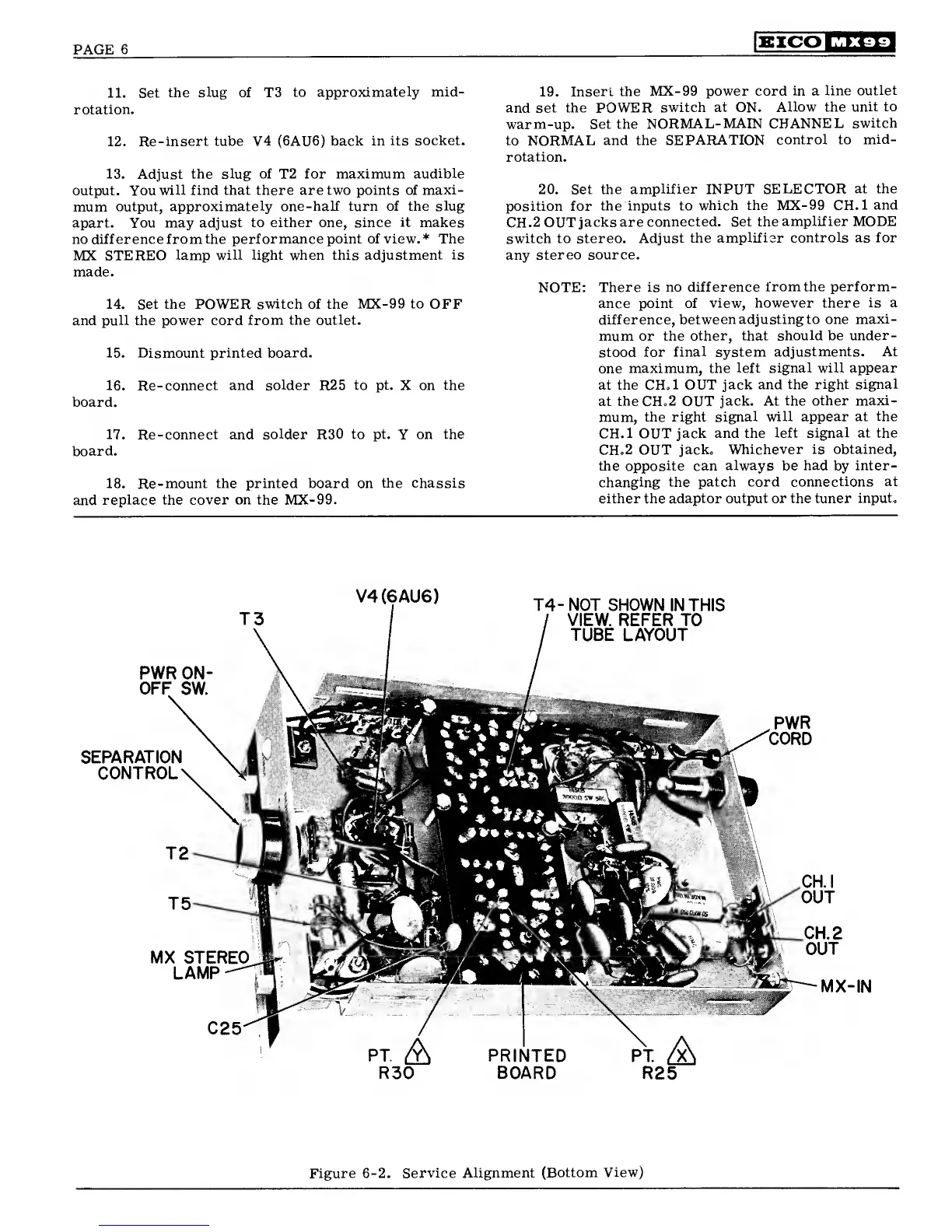
Figure
6-2.
Service Alignment
(Bottom
View)
 Loading...