•1 MX99
PAGE
7
6-3.
VOLTAGE
&
RESISTANCE
CHART
Pin#
Column 1
DC
Volts
Column 2
38KC
Column 3
Resistance
Pin# Column 1
DC Volts
Column
2
38KC
Column
3
Re
si stance
VI 1
100
DC 25K
V3
10
140
DC
6K
2
5.5
DC 2.2M
11
10
DC
2.2M
3
11.3
DC 4,100
12 0
DC 0
5 0
DC
0
V4 1
0
DC
60
6
32 to
50
DC 125K
2
1.5
DC 150
7
-1.3
DC
50-250
3 0
DC 0
8
0
DC
0
4
Filament
-6.3
VAC,
60
cps to ground
9 Filament
-6.3
VAC, 60
cps
to ground 5 140
DC
6,000
140
6,000
V2
1 80
DC 28K
7
1.5
DC 150
2
0
DC 90K
3 2.8 DC 1,500
V5
1
140
16
6,000
4 0
DC
0 0
0
1M
0
DC
0
9.8
5 1.5K
120
DC
15K 0
0
0
13.5 DC 2.2M 5 0
0
0
27
DC 10K
6
140 17
6,000
Filament
-6.3
VAC,
60
cps
to ground 7 -3.2
9
100K
.
8
9.8
1,500
V3
1 Filament
-6.3VAC, 60cps
to ground 9
Filament
-6.3
VAC,
60
cps to ground
110
DC 18K
28 DC 10K
V6 1
AC
280V, 60 cps 370
12 DC 3K
2
—
—
140
DC 6K 3 0
0
0
6 12 DC 3K
4
Filament
-6.3VAC,
60
cps to
ground
7 8
DC 1M
5
—
—
—
8
— — —
6 AC
280V, 60
cps
370
9
8 DC 1M
7
350
2.5
200K*
All
readings are
+20%.
Column
1,
2 and 3: POWER switch to
ON, MX STEREO
switch
to NORMAL,
SEPARATION control to NORMAL.
Feed no signal to inputs.
Column
2: All
measurements are made with a high impedance
VTVM and are at 38kc, unless
otherwise indicated.
Column 3: Line Cord removed from power outlet. Pin 7
of V6 is connected to
ground.
*
Connection to ground removed when making this
measurement.
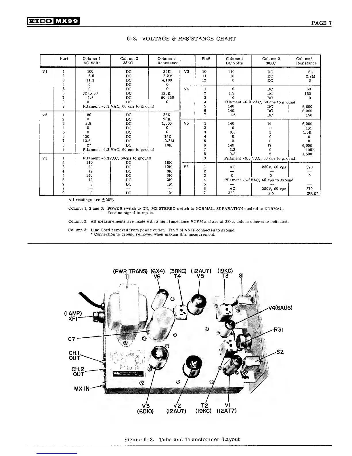 Loading...