This document describes the "Retro Radio" kit, an electronics project designed to introduce users to electronics and provide a sense of achievement through building a functional FM radio. The kit allows for exploration of individual components and gradual assembly of a complex circuit, culminating in a working FM radio capable of receiving local stations with good sound quality. The design is straightforward to assemble, yet offers numerous possibilities for experimentation with different circuits and antennae to receive both nearby and distant stations.
Function Description
The Retro Radio is an FM receiver that allows users to listen to FM radio stations. The core functionality revolves around an FM board, an amplifier, and various passive components like resistors and capacitors. The radio is powered by a 9V battery, with a voltage regulator ensuring the FM board receives a stable 3V operating voltage.
The assembly process is broken down into several steps:
- Mounting the Amplifier: This step involves setting up the LM386 amplifier IC, a 100 µF electrolytic capacitor, a 1 kΩ resistor, and connecting the loudspeaker and battery clip. The LM386 is an eight-legged integrated circuit designed for battery operation, providing 0.5W to an 8 Ohm loudspeaker. Pin 4 (GND) connects to the negative terminal of the battery via a 1 kΩ resistor to limit current, while pin 6 (Vs) connects to the positive terminal. Pin 5 is the output (Vout), to which the loudspeaker is connected via a 100 µF e-capacitor. Pins 2 and 3 are the amplifier inputs.
- Sound Generator: By adding a 10 kΩ resistor to create a feedback loop between pin 3 (non-inverting input) and the output of the LM386, the amplifier is turned into a sound generator, producing humming or clicking noises. This step serves to verify the correct assembly and functionality of the amplifier.
- Improved Amplifier: This step refines the amplifier circuit by replacing the 1 kΩ protective resistor with a piece of wire (to be replaced by a switch later) and adding a 100 nF ceramic disc capacitor at the amplifier input (pin 2). Pin 3 is also connected to GND to reduce distortions. The 100 nF capacitor acts as a coupling capacitor, transferring sound frequency signals. A "buzz test" can be performed by touching the capacitor's wire, which should produce a buzzing or humming sound from the loudspeaker, indicating the amplifier is working.
- Simple Radio: This step integrates the TDA7088 FM IC receiver board and the HT7530 voltage regulator. The voltage regulator provides a stable 3V to the FM board from the 9V battery. An antenna wire (10 cm) is attached to pin A of the FM board. The NF output of the FM board provides the sound signal, which is then fed to the amplifier via two resistors (10 kΩ and 1 kΩ) to moderate the input voltage. At this stage, the radio might already receive a random frequency, and touching the +, S, R, and - contacts on the receiver board can switch to different stations.
- Tuning: This step introduces the scanning and reset functions. The radio IC has a scan input (S) to initiate station scanning and a reset input (R) to return to the lower end of the FM range. Push-buttons (implemented with hook-up wires) are used to trigger these functions. The receiver board also contains a variable capacitance diode (varcap) whose capacitance changes with DC voltage, affecting the frequency. The reset button sets the minimum frequency (around 87.5 MHz) by discharging an integrated capacitor that holds the tuning voltage. Each press of the scan button increases the tuning voltage, scanning for higher frequencies until a new station is found. Automatic Frequency Control (AFC) fine-tunes the frequency.
- Mounting in the Housing: The final step involves integrating the circuit into the provided radio housing. This includes mounting the volume potentiometer (with an integrated switch) and the tuning potentiometer, connecting them to the breadboard, and securing the loudspeaker. The antenna is formed by a 1-meter wire loop threaded through designated holes in the housing. The rotary knobs are then screwed onto the potentiometer axes.
Important Technical Specifications
- Power Supply: 9V battery.
- FM Board Operating Voltage: 3V (regulated by HT7530).
- Amplifier IC: LM386.
- Loudspeaker: 8 Ohm, 0.5W.
- Capacitors: 100 µF electrolytic capacitors, 100 nF ceramic disc capacitors.
- Resistors: 100 Ω, 1 kΩ, 10 kΩ, 220 kΩ (carbon film, 5% tolerance).
- Potentiometers: Volume potentiometer (with switch, non-linear resistance curve), Tuning potentiometer (three-pin).
- Antenna: 1-meter wire loop.
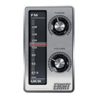
- FM Frequency Range: 87.5 MHz to 108 MHz.
Usage Features
- Easy Assembly: The radio is designed for easy assembly on a breadboard, with clear instructions, diagrams, and photos provided for each step.
- Experimentation: The kit encourages experimentation with different circuits and antennae to optimize reception.
- Volume Control: A volume potentiometer with an integrated switch allows turning the radio on/off and adjusting the volume. The non-linear resistance curve of the volume potentiometer is adapted to human hearing.
- Tuning: A tuning potentiometer allows for continuous scanning of FM frequencies. The 220 kΩ resistor enhances the influence of AFC, simplifying station selection by creating a "lock-in" range. Two additional resistors (1 kΩ and 10 kΩ) limit the tuning range to 87.5 MHz - 108 MHz across the full scale of the potentiometer.
- Station Memory: When the radio is turned on, the previously chosen station will reappear.
- Reception Improvement: Users can try turning the radio or antenna, or relocating the radio near a window, to improve reception, especially for fainter stations.
Maintenance Features
- Troubleshooting Guide: The manual includes a comprehensive troubleshooting section to help identify and resolve common issues such as incorrect wiring, short wires, bent IC pins, connection problems at the battery clip or switch, and exhausted batteries.
- Diagnostic Tests: Specific tests are outlined, such as touching amplifier pins or capacitor terminals to check for clicking/humming noises, and using a voltmeter to check voltages at various points (BAT pin, GND pin, NF output, tuning potentiometer wires) to pinpoint problems.
- Component Check: The guide advises checking if the amplifier or voltage regulator heats up, which could indicate an improper connection. Jiggling wires and components can help identify loose contacts.
- Component Replacement: While rare, components can be faulty or damaged by excessive voltage. The guide implicitly suggests that if troubleshooting points to a faulty component (like the loudspeaker, amplifier IC, or FM board), replacement might be necessary.
- Cleaning: Connection problems due to deformation or contamination are mentioned, implying that ensuring clean contacts is part of maintenance.
The Retro Radio kit provides a hands-on learning experience in electronics, from basic component understanding to assembling a functional device, with features designed for both educational value and practical use.