Label L1, L2 and L3. (Arbitrarily assign labels.)
You will be using 3 CTs for this install. Label them CT1, CT2 and CT3.
Fit CT1 around L1. Make sure the arrow is facing towards the load (in
the direction of ow).
Fit CT2 around L2.
Fit CT3 around L3.
Black wire from CT1 connects to Port 1 on the Omnimeter. White wire
from CT1 connects to Port 2. (Fig 5)
Black wire from CT2 connects to Port 3 on the Omnimeter. White wire
from CT2 connects to Port 4. (Fig 5)
Black wire from CT3 connects to Port 5 on the Omnimeter. White wire
from CT3 connects to Port 6. (Fig 5)
With split core CTs, close the CT around the wire to be measured and
press rmly until you feel and hear it click to indicate full closure. The
buttons should be fully out. Use a zip tieto ensure the CTs remain
securely closed.
Use a max 1.0 Amp inline fuse on each line to protect the meter.
To power the meter and get a voltage reference: Tap into L1 at the
breaker panel. Connect one fuse holder pigtail to the breaker, lug or an
appropriate line-tap device, and connect the other pigtail to 16-22
AWG UL rated stranded copper wire for connection to the meter. L1
connects to Port 7. Tap into L2 and L3 and repeat the connection
process. L2 connects to Port 8. L3 connects to Port 9. Neutral
connects to Port 10. (Fig 5)
Once the meter is properly mounted to the DIN Rail or enclosure and
all wiring is completed, with terminal block covers installed, power can
be turned back on.
Meter will then begin cycling through meter values. For details, go to:
http://documents.ekmmetering.com/EKM_Metering_LCD_Display_Value_Reading.pdf
A video of proper install of a 120V-208V, 3-Phase, 4-Wire system can be
found here: http://www.youtube.com/watch?v=DeKiZddR0K8
1.
2.
3.
4.
5.
6.
7.
8.
9.
10.
11.
12.
13.
14.
eKM Metering Inc.
EKM Metering Inc. – www.ekmmetering.com – info@ekmmetering.com – (831)425-7371
RS-485 and Pulse Output:
• Terminal 11 (A) connects to RS-485+ or T+ on the RS-485 network. Terminal 12 (B) connects to RS-485- or T-. Terminal 13 (G) is used for the RS-485
network (signal) ground if needed. Observe proper RS-485 network topology. Twisted pair wiring is recommended. Shielded twisted pair may be
benecial in electrically noisy environments or for very long runs. RS-485 supports up to 256 devices on up to 4000 feet wire. Terminating resistors
may be benecial.
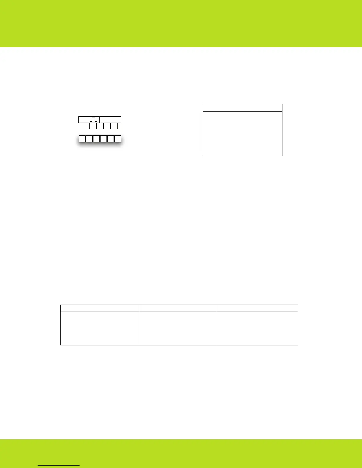
• Terminals 14 and 15 are for pulse output. Pulse rate: 800 Impulse/kWh when set to 200A. Polarity sensitive. Maximum 27VDC, 27mA.
• Red LED on the meter face ashes 800 times/kWh(1 ash = 1.25Wh) when set to 200A.
All EKM meters, including the Omnimeter I v.3, have a Pulse Output. The Pulse Output pulses at a rate of 800 pulses per kilowatt hour when set to use
200 amp current transformers. This is the same rate that the red LED ashes on the meter face — 800 times/kWh. These are unpowered electronic dry
contact pulses that can be counted by standard electronic pulse counters. Pulse counters can be located up to 200 feet away from the Omnimeter.
*Note: Some Omnimeter I v.3 meters have a slightly different conguration for the pulse output terminals. These meters are identiable by a sticker on
the meter case showing the different conguration. In the case of these meters, please follow the direction of the sticker, not of this spec sheet.
Working Principle:
When the meter is working, the energy consumed by the user is transformed into voltage and current signals, which are sampled by sample circuits. A
pulse signal is then produced by a specialized IC. The Pulse signal is directly proportional to power consumption. The MCU records and stores the
corresponding energy use. The LCD screen displays the energy use. Recorded information and data can be transferred using the RS485 interface.
Data:
The LCD display shows 15 pieces of data: total energy consumption(kWh), reverse kWh, voltage L1,voltage L2,voltage L3, current(Amps) L1, current L2,
current L3, power(watts) L1, power L2, power L3, total power(watts), COSθ(power factor) L1, COSθ L2, and COSθ L3. Every ve seconds the LCD screen
will display a new piece of data. The meter also provides max demand(kW) data and the demand period can be set to one of three intervals:
15minutes, 30 minutes, or 60 minutes. The max demand can be reset to zero in software over RS485. The meter has four time-of-use tariffs(T1, T2, T3,
T4) to calculate the power during different time periods, and it can set up to four time periods per day, and specify the number of the tariff for that
period(from T1 to T4). The meter time can be set using the RS485 interface. By design the kWh cannot be reset. The meter will go at least 30 years
without power and still keep its kWh readings. In other words, the memory will not be erased if there is no power. See Figure 8 for meter display values:
Transport and Handling:
The meter should be handled with care, as there are precision components inside that could break and/or cause faulty readings should the meter
become damaged. The process of transportation, handling, and installation should be done according to the transportation and storage rule of
GB/T15464-1995. Keep the meter in the original packaging when stored. The storage temperature range should be 0–40ºC. The relative humidity
should be ≤85%. There should be no toxic chemicals present and no corrosive substances or gases in the air. The meters should be stacked on a
platform no more than ten units high.
Warranty:
Within two years from the date of sale, and on the condition that the user abide by the specications and installation instructions listed here, and the
sealing is kept completely intact. If the meter does not correspond with the rule of the enterprise standard, the meter shall be repaired free or replaced.
16
15
14 13 12 11
SO RS485
_
+
G
A
B
#
11
12
13
14
15
LCD Display Data
Watts L3
Watts Total
Cosϴ L1 (Power Factor)
Cosϴ L2
Cosϴ L3
#
06
07
08
09
10
LCD Display Data
Amps L1
Amps L2
Amps L3
Watts L1
Watts L2
#
01
02
03
04
05
LCD Display Data
Total kWh (forward + reverse)
Reverse kWh
Volts L1 (Line 1)
Volts L2
Volts L3
(Fig 8)
CT Ratio Impulse Constant
100/26.6 1600
200/26.6 800
400/26.6 400
800/26.6 200
1500/26.6 106.67
3000/26.6 53.33
5000/26.6 32
(Fig 7)
(Fig 6)
 Loading...