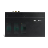
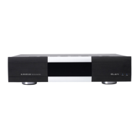
HC4
Quick Install Guide
Rev. C - 3/10/11
P/N 9901084
DO NOT connect the DC power cord until all other connections have been completed.
1
Unpack the HC4. Verify that you have all package contents. You should have received:
HC4 DB9 Male to RJ45 Adapter (4) Mounting Screws (4)
12VDC Power Supply Safety Sheet HCREM Remote
AAA Batteries (2) Can Brackets (2) Quick Install Guide (This Document)
Mount the HC4 in the desired location.
When choosing the location for the HC4 keep heat management and ventilation in mind. The HC4 should not be
directly located above heat sources such as amplifiers. In very warm locations (i.e.: enclosed cabinet) leave space
above and/or below the HC4. For can mount applications, use the optional mounting hardware.
Serial Connections
Connect up to 4 RS232 controlled devices using the included DB9 to RJ45
adapters. One RS485 ports is also available for a total of 5 serial ports.
Connect serial inputs from PPIS panels when using GCIREs. Suggested
Cat5 wiring is 568 for the RS232 port connections to the DB9-RJ45
adapters. Refer to the Integration Notes for Cat5 wiring for devices
connected to the RS485 port.
VIA!Net Connections
Connect to PPCM precision panel to provide VIA!Net
communication for TS2 user interfaces connected to
PPVN panels or to other supported VIANet devices.
Insert wires in this order:
Blue
White/Blue
Orange
White/Orange
Green
White/Green
Brown
White/Brown
1 2 3 4 5 76 8
PR3
GR
PR2
OR
PR1
BL
PR4
BR
ELAN Standard
Relay Connections
Connect to the PPCM precision panel to activate relay controlled devices like lifts, drapes and
movie screens located in the zones. Connect bare leads using the screw down terminals. Only
Room connections 1-2 on the PPCM have relay connections. Accepts up to 24V AC or DC and
current of up to 1 amp. Relay controlled devices may be directly connected if desired.
Sense Input Connections
Connect to the Sense Input connections of the PPCM using 3.5mm stereo cables. This allows
ELAN sensors connected to PPRMs to be used to trigger events or to be used when conditionals
are required in programming. The connection from the HC4 provides power for the sensor.
Optionally, sensors may be connected directly to the HC4 sense inputs.
IR Output Connections
Connect to IR controlled devices at the head end or by using the PPCM to connect to
IR controlled devices located in zones. Use 3.5mm mono cables to connect to the
PPCM.
EXTERNAL IR Input Connection
Connect to the EXT IR IN connection of a PPVN or the PPCM. This connection allows the HC4 to
receive IR input from a TS2’s IR receiver (through the PPVN) or from an IR sensor connected to a
PPRM, PPIS or PPIR (through the PPCM). If you need to connect both the PPCM and a PPVN to
the EXT IR In of the HC4 an IR connecting block can be used. An IR sensor can be directly
connected if desired, for example, when used in Home Theater applications.
Audio Output Connection
Connect to a source input of the A/V Controller. This is the line level audio output of the
Internal Player. Requires a 3.5mm stereo mini to RCA adapter.
Video In/Out Connections
Connect the Video Output to the component input of a monitor to provide the On Screen
Display of the HC4. Connect the Video Inputs to the component video output of the A/V
Controller to allow video to loop through the HC4 when the OSD is not being displayed.
Ethernet and USB Connections
Connect the Ethernet connector to a switch or router to allow the HC4 to communicate on
the network.
Connect the USB connection to the dial-up modem for Voice Mail applications.
Connect DC Power Cord
Verify the HC4 is powered using the Activity Indicator LEDs.
Verify the HC4 is on the network
Using the g! Configuration software verify the HC4 is on the network. You can also “ping”
the HC4’s IP address from a computer that is on the network.
The HC4 comes from the factory as a DHCP client. We recommend changing the IP
address using the “Config IP Info” button on g! ConnectPro to a dedicated static address
outside of the DHCP range of your network.
2
3
4
5
6
7
8
9
10
11
12
13
To help protect your equipment from power surges and momentary power interruptions, we
strongly suggest that you use a battery-backed power supply (UPS) with this equipment.
The complete HC4 Installation manual and the current Core Module software can be found and
downloaded by going to www.elanhomesystems.com and following the dealer link. Be sure to
update the HC4 to the current Core Module software prior to programming.
Precision panel documentation is also located on the dealer site.