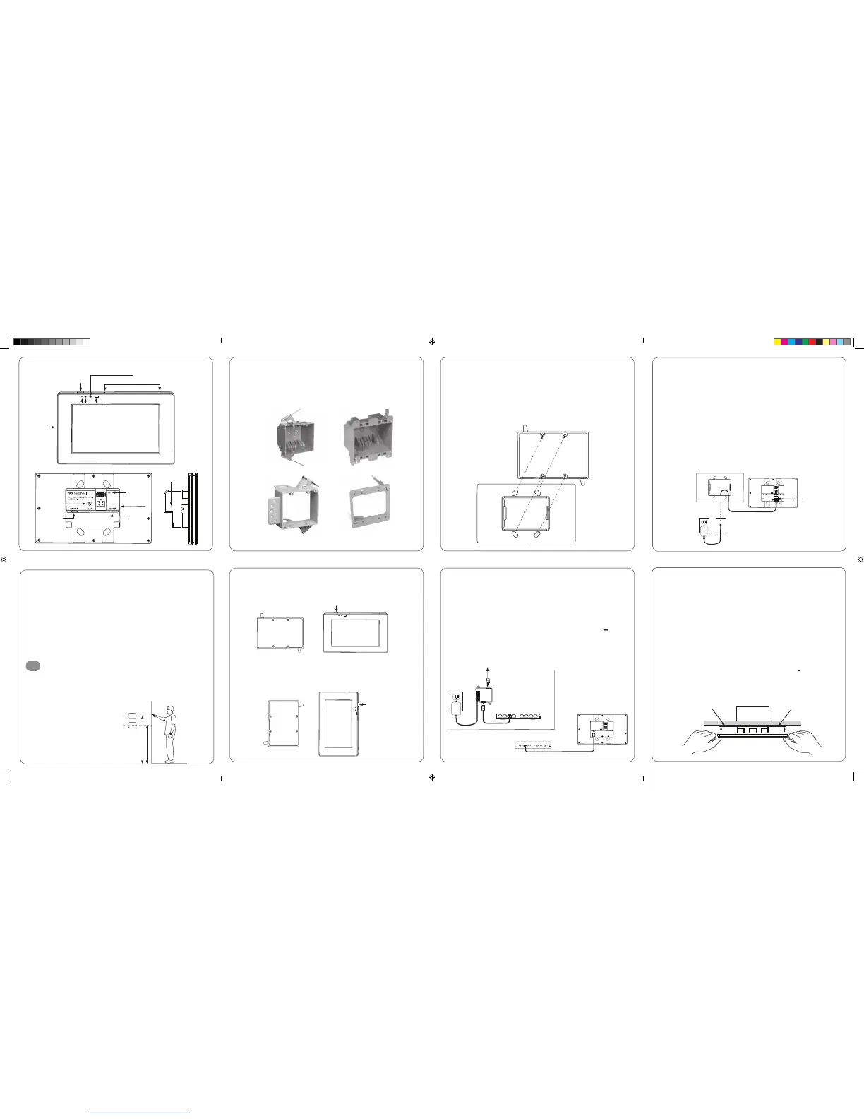
Planning the installation
1
New Const. Box
Old Work Box
b. Rough-In
The TP7 has been designed to mount to a US standard 2 gang box or low voltage bracket.
- The TP7 is “snap” fit into the box/bracket and requires approximately 10lbs of force
to remove it from the wall. Ensure that the mounting method you are using is compatible
with these requirements.
c. Landscape Mounting
– Install the 2 gang box or bracket in it’s normal orientation – with mounting screw holes
at the top and bottom. The box is exactly centered with the touch panel for your convenience.
d. Portrait Mounting
– Install the 2 gang box or bracket rotated 90° - with the mounting screw holes on the left
and right sides. The box is exactly centered in the touch panel for your convenience.
e. Installing the TP7 Bracket
– The TP7 includes a mounting bracket that MUST be used. Using the included screws mount
the bracket onto the 2 gang box or low voltage bracket and verify that the bracket is level
before tightening the screws.
– The mounting bracket is designed to level out uneven wall surfaces allowing the TP7 to fit
securely on most any surface. Note that uneven surfaces will create a gap between the back
of the panel and the wall – this is normal. Do not tighten the mounting bracket so as to
distort it’s shape as this will create issues with properly seating the TP7 in the bracket.
12v Power Supply
– By utilizing a 12v power supply (not included) to power the TP7 you may provide power
locally or remotely. If powering locally be sure to run the wire through the wall
in accordance with local codes. If powering remotely be sure to use wire of adequate
gauge for the length of the run.
– Verify the polarity of your power supply prior to termination and ensure the power
supply is not connected to a power source.
– Strip approx. ¼” of insulation from the wire and observing the correct polarity, terminate
the wire into the supplied connector and tighten firmly. Be sure to twist the wires before
inserting so that no strands escape the connector. Inspect the termination to verify that
the wire is securely retained by the connector and no strands have escaped the barrier.
– Plug the connector into the TP7.
f. Connecting the TP7 to power
– The TP7 is designed to be powered over the Ethernet connection (PoE) or by connecting
a 12v power supply (not included), but not both. If both the PoE and a 12v power supply
are connected the TP7 will draw power from the 12v source.
PoE Connection
– PoE connection requires that IEEE 802.3af standard (13w maximum draw @48 V @270 mA)
is met. Utilize a network switch or PoE injector that meets this standard.
– Connect the TP7 using a standard T568A or T568B Ethernet cable from the network switch
to the LAN/PoE jack. If you have terminated your own CAT 5e/6/7 cable use a tester
to ensure that both ends have been properly terminated.
g. Connecting Ethernet
– When not utilizing PoE, but you have a physical network connection available it
is recommended that you connect the TP7 directly to the network switch.
– Utilizing a T568A or T568B network cable connect to the LAN/PoE jack.
If you have terminated your own CAT 5e/6/7 cable use a tester to ensure that both
ends have been properly terminated.
h. Mounting the TP7
– The TP7 is held into the mounting bracket by spring steel tabs.
– Orient the TP7 with the POWER button at the top right for landscape mounting
or the top left for portrait mounting.
– To complete the installation simply grasp the TP7 on the edges and press firmly on to
the bracket until it is seatled.
CAUTION: DO NOT PRESS DIRECTLY ON THE SCREEN
when installing on to the mounting bracket. Press only on the frame edges.
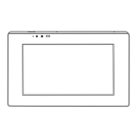
The TP7 is designed to wall mount in either Portrait or Landscape orientation.
Ensure there is adequate wall space for the TP7 and that the surface is relatively smooth.
The TP7 requires a minimum mounting depth of 1 ¾” (4.5 cm) from the front surface
plus room for wire. Ensure that adequate depth is available.
Power may be supplied by Power Over Ethernet (PoE) or by a 12v DC power supply (not included).
PoE must meet the IEEE 802.3af standard. Direct power via a 12v DC external power supply
requires a minimum current output of 1A.
The TP7 connects to the local network via Ethernet or Wi-Fi. When utilizing Wi-Fi you must
ensure that there is adequate Wi-Fi coverage at the mounting location.
Installing the TP7
a. Mounting height
– Depending on how tall your homeowner is, it is recommended to locate the center
of TP 7 between 57”- 65” (145 cm -165 cm) above the finished floor.
165 cm / 65”
145 cm / 57”
New Const. Low Volt Bracket Old Work Low Volt Bracket
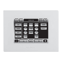
TP7 – Overview
USB
DC Power
Input
LAN + Power
over Ethernet
Network Switch
PoE Injector
Audio Out
(Future Use)
Power
Microphone
Camera
Status LED
Speaker
Proximity Sensor
Power
Power
Recessed
Reset Switch
TP7 Touch Panel
 Loading...