1 2
3
4
ON
a b T T L
5
9
Anschlussklemmblockabziehbar
Leiteranschließen:
Leiterlösen:
Leitereinfacheinstecken.
(Massivleiter 0,4-0,8mm)
OrangenenDrückerbetätigen.
Leiterherausziehen.
Ø
Mikrofon
Moosgummi
Montage:Briefkasten-Anlage
ZurVerbesserungderakustischen
EigenschaftensolltedasMikrofonmittels
einesSchraubendrehersnachvorne
herausgeschoben,undmitbeigefügten
MoosgummidirektanderSchallein-
trittsöffnungbefestigtwerden.
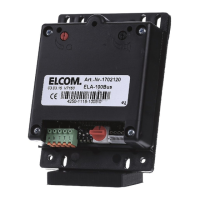
Beschreibung:
1. Anschlussklemmen
2. Betriebsartschalter
3. Drehcodierschalter
4. Anschlußfüri2-BUSTastenexpander(BTE-116)
5. Lautstärkeregler
6. Mikrofonregler
7. GrüneLED: Sprechverbindung
8. RoteLED: AbgehenderRuf
9. ÖffnungzumHerausschiebendesMikrofons
Klemmea/b: ELCOMi2-BUS
Klemme T/T: potentialfreier TüröffnerSchaltkontakt(max.24V/1A)
KlemmeL: Lichttasteranschluß(GegenpolKlemmeaoderb)
Schalter1: OFF= Audio-Türstation ON=Video-Türstation
Schalter2: OFF= TüröffnungnurbeiVerbindung
Schalter3: OFF=Quittierungstöneausgeschaltet ON=Quittierungstöneeingeschaltet
Schalter4: keineFunktion
(rot)
Stellung0-9: Adressenfür TürlautsprecherimHauptstrang
Stellung A-F: Adressenfür TürlautsprecherimNebenstrang(Laubengang)
ON= Türöffnungjederzeit
ACHTUNG: AdressendürfenimStrangnichtdoppeltvergebenwerden.
AN_ELA-100_DE_110216
ELA-100 Türlautsprecher
1 2
3
4
ON
a b T T L
Hotline: hotline@elcom.de
1 2
3
4
ON
a b T T L
99
28.5
14
7x3.5
42
75
42
62
62
D3.5
6.75
10x3.5
25
44
4.5
6
27,5
1 2
3
4
ON
a b T T L
TechnischeÄnderungen,IrrtümerundDruckfehlervorbehalten.
Art.Nr.:0221103
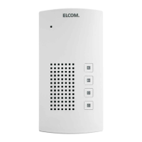
ELCOMSprechgitter
MontagemittelsHaltebügel
ELCOMSprechgitter
BittebeachtenSieauchunserebebilderten
EinbauanleitungenfürdierichtigeMontagedes
TürlautsprechersindiverseFremdklingelplatten
oder-briefkastenanlagenwiez.B.RENZoderJU.
SiefindendieseinunseremDownloadbereichunter:
unddortunter:
TechnischeDokumente
TürstationenundBriefkästen
http://www.elcom-portal.de/webexplorer/
01
07
ELA_Anleitungen_Briefkasten_Einbau
MontageamELCOMSprechgittermitHilfeder
beigefügtenSchrauben(M3x8).
Mikrofon
Moosgummi
AchtenSiebeiderMontageauf
freienSchallein-undaustrittan
MikrofonundLautsprecher.Zur
Verbesserungderakustischen
EigenschaftenkanndasMikrofon
mitHilfeeinesSchraubendrehers
nachvorneherausgeschoben,und
mitbeigefügtem Moosgummidirekt
anderSchalleintrittsöffnung
befestigtwerden.
Briefkasten/Sprechfach
Haltebügel
Einbauhinweise
ESTA /MODESTA Stationen