Choice of Charging Curve (curve 1~10)
1.The LED will flash red several times when AC is first connected, then the LED will
flash green once. The number of red flashes denotes the present curve. E.g. If the
red flashes three times, it means the present curve is curve 3.
2.To choose another curve, cut off the power supply first, then unpeel the label and
press the button while connecting the power. If you want curve 3, release the button
after the 3
rd
LED Flash. Now the selected curve (e.g. curve 3) will be recorded in
memory.
Alarms
LED Flashing Sequence(One
Cycle)
Indication
1 R G _ _ _ _ _ _ Wrong Battery
2 R G R _ _ _ _ _ Overcharged
3 R G R G _ _ _ _ The temperature of battery is too high
4 R G R G R _ _ _ Incorrect AC Input Voltage
5 R G R G R G _ _ The thermal sensor of charger is in fault
6 R G R G R G R _ The interface of communication is in fault
7 G R _ _ _ _ _ _ The temperature of charger is too high
8 G R G _ _ _ _ _ The relay of charger is in fault;Repair
9 G R G R _ _ _ _ Charger is in fault; Repair
Note:
1. R—red G—green
2. “_” denotes one second stop
1. Above LED flashing sequence is just one cycle, the LED repeat when in fault
Installation & Safety Instructions
Our charger has been designed to provide safety and reliability. It is important to
observe the following precautions and installation instructions in order to avoid
damage to persons and to the battery charger. For further reference keep the
instruction in a proper place.
1. Fix the battery charger to a stable surface with the holes inserted on the mounting
tabs. In case of installation on a vehicle, it is advisable to use anti-vibration supports.
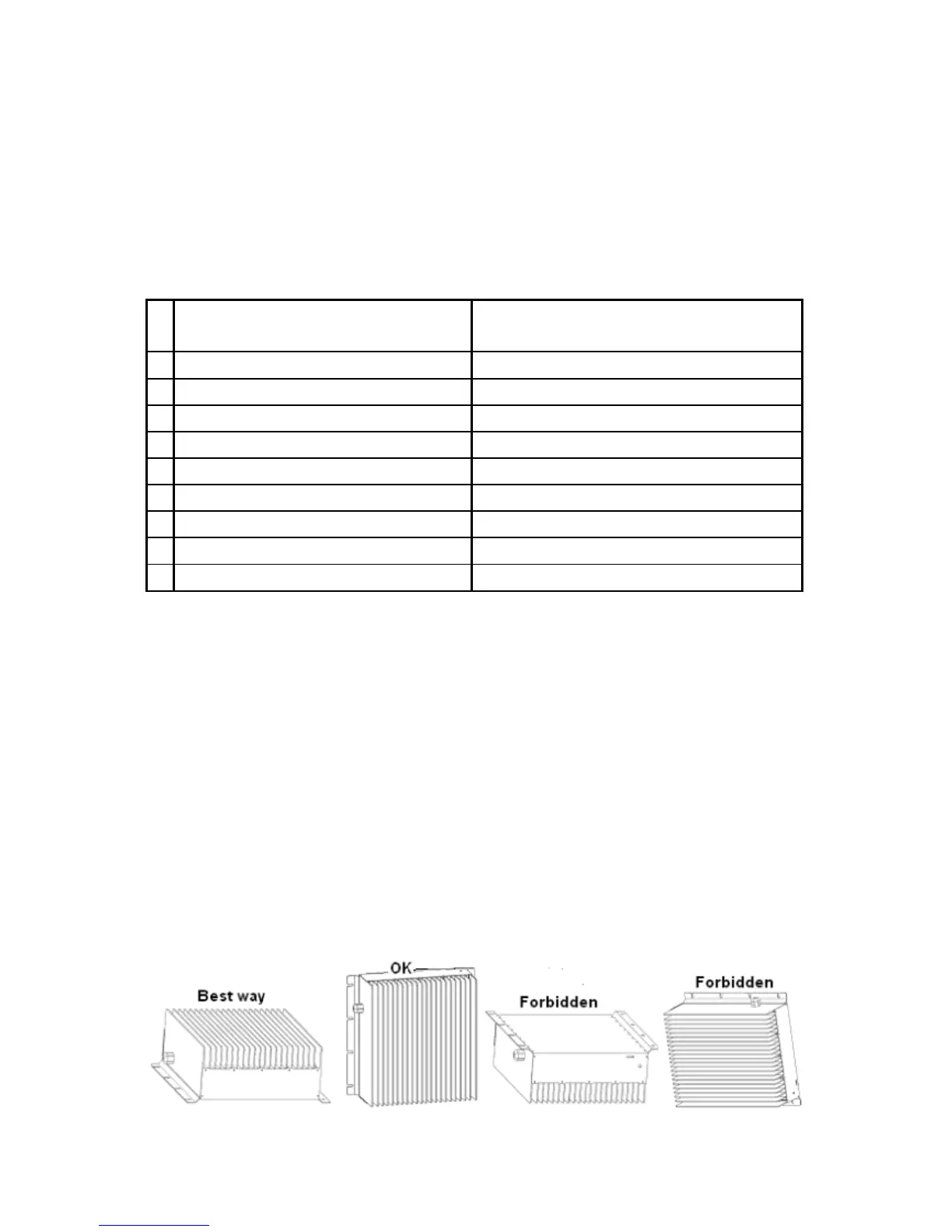
2. Preferably the charger should be installed in the vertical position with radiator fins
vertical. A space of 10cm above ground should be open, to ensure it is ventilated.
Never install in the vertical position with fins facing down. Refer to drawing below:
3. Ensure all heat-dissipating parts are not obstructed to avoid overheating. Do not
 Loading...