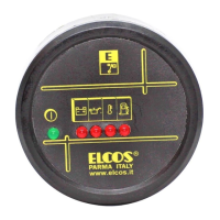
The ELCOS DIP-804/00 is an engine protection device designed to monitor the functioning of a diesel engine and initiate a shutdown if anomalies are detected in the parts controlled by probes. It is suitable for installation in dashboards, electric panels, or other cavities.
Function Description
The device surveys the engine's operation and stops it in cases of anomaly related to:
- Inefficient battery charge alternator (e.g., belt breakage)
- Low oil pressure
- Overheating
It also provides an indication for fuel reserve without stopping the engine. Oil and battery indicators are integrated into the device.
Technical Specifications
- Battery Supply Voltage: 12 VDC (max 16 VDC) or 24 VDC (max 32 VDC)
- Circuit Loading with Key Turned to Zero: 8 mA
- Maximum Load on Output [5] (STOP): 3 A
- Maximum Load on Output [7] (GENERAL ALARM): 3 W
- Temperature Range: -10 ÷ +60 °C
- Terminal Board: FASTON 6.35 × 0.8
- Degree of Protection:
- For the electronics: IP 65
- For the terminal board: IP 00
- Weight: 450 g
Usage Features
The device utilizes an ignition key (mounted externally) with three positions:
- REST: Manual stop, reset protection.
- AUT.: Device supply.
- START: Start engine.
Twin-Function Indicators:
- Oil and Battery Indicators: These illuminate when the key is turned to "AUT" and switch off when the engine is running, and oil pressure and battery recharger are regular.
- Anomaly Indicators: These are enabled after the "ENGINE PROTECTIONS ACTIVE" indicator (①) switches on, and they illuminate when a relevant anomaly is detected.
Engine Protections:
Engine protections are enabled 20 seconds after turning the key to "AUT" or 20 seconds after the end of the start impulse, indicated by the "ENGINE PROTECTIONS ACTIVE" (①) light. Protection probes (mounted on the engine) trigger a shutdown, indicated by visual indicators, and are divided into two groups:
- Immediate Stop: For oil pressure switch and overheating thermostat.
- Stop after 3-second delay: For battery charge alternator (alternator belt breakage).
Alarm:
A fuel reserve alarm is enabled when the ignition key is turned to "AUT" but does not stop the engine.
Stopping Mechanisms:
Stopping can be achieved in three ways:
- By turning the ignition key to zero.
- Due to protection intervention.
The device uses two types of stoppage:
- Activating an electromagnet to pull the STOP lever for 20 seconds.
- Disconnecting the supply to the solenoid, which closes the gasoline passage. The system is configured by default for solenoid stopping; for electromagnet stopping, terminals 39 and 40 must be connected.
Main Alarm:
A visual and/or acoustic indicator can be externally connected to the relevant output. This alarm is continuously activated if protections or the fuel reserve alarm intervene.
Reset:
Resetting the device is achieved by turning the ignition key to zero.
Device Test (Simulation):
The manual outlines procedures to simulate interventions for recharge alternator (belt breakage), low oil pressure, overheating, and fuel reserve by disconnecting specific wires and connecting them to earth. This allows testing the device's response and the activation of general alarm and visual indicators.
Engine Probes Test (with probes disconnected):
Detailed test procedures are provided for recharge alternator, low oil pressure, overheating, and fuel reserve, outlining expected indicator behavior in various engine states (stationary, running with regular belt/pressure/temperature, running with broken belt/insufficient pressure/overheating, or running out of fuel).
Troubleshooting:
The manual includes a troubleshooting guide for common issues:
- Starter motor functions but engine does not start: Probable causes include lack of fuel, fuel supply circuit defect, or low temperature. Remedial actions involve filling the tank, checking the stop system (solenoid/electromagnet), consulting the engine manual, and checking preheating functions.
- Engine stops for anomaly: Probable causes include belt breakage, low oil pressure, or overheating, indicated by the respective lights. Remedial actions involve checking the alternator belt, engine oil level, or engine cooling system.
- Engine does not stop under any conditions: Probable causes include a non-functioning stop system (electromagnet/solenoid), defective engine probes, or a defective device. Remedial actions involve checking the stop system, testing/replacing probes, and simulating/replacing the device.
- Engine stops for anomaly though all appears to be regular: Probable causes include belt breakage, low oil pressure, or overheating (indicated by lights) or a defective device. Remedial actions involve checking the charge alternator, testing/replacing the oil pressure switch or thermostat, and simulating/replacing the device.
Maintenance Features
The following maintenance operations should be performed weekly:
- Check that the indicators function.
- Check the batteries.
- Check that the conductors are tight and inspect the condition of the terminals.
Important Notices:
- Always install away from equipment that produces or spreads heat.
- Follow the circuit diagram for connections.
- Ensure compatibility of line loading and consumption with technical characteristics.
- Perform all technical interventions with the engine stationary and terminal 50 of the starter motor disconnected.
- Never use a battery charger for emergency start-up, as this can damage the equipment.
- Disconnect electrical plant terminals from battery poles before connecting an external battery charger for safety.
- The hole in the casing used for installation can affect protection levels; steps must be taken to maintain the original level of protection.
- The device is not suitable for extreme environmental temperatures, high radiation levels, fire/explosion risks, or strong vibrations/knocks.
- The device functions correctly only in CE-compliant plants and meets EN50082-2 exemption requirements, though malfunctions in extreme cases are possible. The installer must ensure disturbance levels meet standards.
- The panel is not suitable for use in critical equipment or plants responsible for keeping persons or other living beings alive unless a written declaration states otherwise.