Do you have a question about the ELECRAFT T1 and is the answer not in the manual?
Explains how to initiate autotuning and interpret SWR readings via LEDs.
How to obtain SWR, battery voltage, and other parameters via Morse code.
Procedure for testing relays and L-network components using test mode.
Explains bidirectional data transfer for band information and settings.
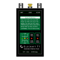
The Elecraft T1 Automatic Antenna Tuner is a compact, stand-alone device designed to optimize antenna performance for low-power HF through 6-meter transceivers. Its primary function is to match the impedance of an antenna to that of a transceiver, ensuring efficient power transfer and reducing standing wave ratio (SWR). The T1 is suitable for various applications, including home, mobile, camping, and HF Pack use.
The T1 operates as an L-network tuner, utilizing a combination of seven inductors and seven capacitors to achieve a wide range of impedance matches. The capacitance can be switched to either the transmitter or antenna side of the network, providing flexibility in tuning. The device employs latching relays, which means they only consume power during tuning operations, significantly extending battery life.
A key component of the T1 is its microcontroller (MCU), which manages the tuning algorithm and user interface. The MCU controls the selection of inductor and capacitor values through the relays, aiming to find the lowest possible SWR. The tuning process involves a comprehensive, three-stage algorithm that explores 32,768 possible relay combinations. This algorithm includes coarse, fine, and very fine matching stages, progressively narrowing down L/C groups to achieve an optimal match. To speed up tuning, the T1 saves successful match settings in its EEPROM, allowing for faster retunes on previously used bands.
For SWR and power measurements, the T1 incorporates a directional coupler. This bridge is inherently balanced across a wide frequency range and requires no adjustment. The bridge outputs are fed into the MCU's analog-to-digital inputs, which then convert these voltages into SWR and power readings. The MCU uses averaging and linearization techniques to enhance accuracy. Before tuning, the T1 determines the peak power of the transmitted signal, using this value to qualify SWR readings. This allows for accurate antenna tuning using various modulation methods, including SSB voice and CW keying, without significant loss of accuracy compared to using a constant carrier.
The T1 also features a remote control interface (J3) that allows external devices, such as transceivers or computers, to control its functions. This interface supports both a TUNE signal and a bidirectional DATA signal. The DATA line enables the T1 to request and receive band information from a control device, allowing it to store and recall network settings on a per-band basis. This feature is particularly convenient as it enables the tuner to track band changes at the rig without requiring manual intervention or transmission.
The T1 is designed for straightforward operation with a simple user interface consisting of two switches (PWR/TUNE and BYP/INFO) and three LEDs (Green, Yellow, Red) that indicate SWR, power, and status.
To initiate autotuning, the user holds the PWR/TUNE switch until the green LED illuminates and flashes. The user then transmits while the green LED is flashing (approximately 3 seconds). The T1 will perform the tuning process, and the LEDs will display the approximate SWR. Intermediate SWR values are indicated by combinations of LEDs (e.g., Green+Yellow for 1.5:1, Yellow+Red for 2.5:1). Initial tune-ups typically take about 5 seconds, but subsequent retunes are much faster due to saved settings. The T1 automatically turns off after tuning, preserving the settings with its latching relays.
For faster retuning with difficult loads, the T1 offers an option to select a 2:1 SWR threshold for saving and retuning. This is activated by holding the PWR/TUNE switch until the green LED turns on and then off, before transmitting.
To view approximate power output, the user taps the PWR/TUNE switch (a press shorter than 0.5 seconds). The yellow LED will flash, and the user should begin transmitting within 3 seconds. The LEDs will then indicate power levels: Green for 0.5-1.5 W, Green+Yellow for 1.5-3 W, Yellow for 3-5 W, Yellow+Red for 5-8 W, and Red for over 8 W. If power drops below 0.5 W for 3 seconds, the T1 will automatically turn off.
The T1 can be bypassed, setting both L and C to zero, which is useful for adjusting antennas to resonance. To bypass, the user taps PWR/TUNE (yellow LED flashes), then taps BYP/INFO to toggle between ATU in-line (green LED) and bypassed (yellow LED). Even when bypassed, the T1 can still show SWR by activating TUNE mode and keying the transmitter.
The INFO feature provides detailed information about the last SWR reading, battery voltage, and other parameters. To access this, the user taps PWR/TUNE (yellow LED flashes), then holds BYP/INFO for about 1 second. The T1 will send parameters in slow Morse code via both the yellow LED and a weak RF signal. Parameters include SWR (Sx), battery voltage (Vx), inductance (Lx), capacitance (Cx), network configuration (Nx), band ID (Bx), and firmware revision (Fx). The report can be cancelled by holding PWR/TUNE for about 1 second.
The T1 supports remote control via its J3 jack. An external PWR/TUNE switch connected to J3-ring can enable auto-tuning. The DATA line (J3-tip) allows for bidirectional communication, enabling the T1 to request band information and store/recall network settings on a per-band basis. This means the tuner can track band changes at the transceiver without needing to transmit.
The T1 is compatible with a wide variety of antennas, including dipoles, verticals, whips, beams, and random-length wires. It is crucial to use a good ground counterpoise for efficient transmission, especially with verticals, whips, and end-fed antennas. For coax-fed antennas, the T1 can extend their frequency range. For random-wire antennas, wire length, height, and ground system are important factors, and certain lengths should be avoided. The T1 can also extend the range of loaded and short antennas, often allowing full-band operation. When using loaded antennas, it's recommended to manually resonate the antenna in bypass mode first, then use the T1 for fine-tuning. While the T1 always tries to achieve 1.0:1 SWR, a slightly higher SWR (e.g., 2:1) often results in minimal signal loss. Using a balun (e.g., a 4:1 balun) can improve impedance matching, allow balanced feedlines, and reduce RF pickup.
The T1 is powered by an internal 9-V battery. To install, the user slides open the battery compartment cover and aligns the battery's negative terminal with the wider contact. The T1 includes reverse-polarity protection. For transport, the battery can be removed and re-installed flipped to prevent accidental power-on.
On power-up, the T1 checks the battery voltage. If it's low, the red LED will flash twice, prompting the user to replace the battery. The actual battery voltage can be checked via the INFO report.
The manual provides guidance for common issues:
The T1 includes a test mode to troubleshoot relays and L-network components. To enter test mode, the user taps or holds PWR/TUNE, then holds BYP/INFO for over 4 seconds. The T1 will send "L0" in slow CW on the yellow LED, indicating L=0 (C is also 0). Tapping BYP/INFO allows selection of individual L and C values (L1-L7, C1-C7) and network configurations (C TX/C ANT). Relays can also be controlled by sending binary data via J3. This mode is useful for connecting an SWR bridge between the T1 and transmitter with a 50-ohm load to test the effect of each component on SWR. The T1 automatically turns off after 60 seconds of inactivity in TEST mode.
If the T1 needs to be opened for testing or parts replacement, it is crucial to use an anti-static mat or periodically touch a grounded metal surface to prevent electrostatic discharge (ESD) damage to sensitive components. The interior is accessed by opening the battery compartment and removing four screws from the bottom. The LEDs and switches are on the Control board, which plugs into the Main board. The microcontroller (U1) is located beneath the Control board.
| Frequency Range | 1.8 - 54 MHz |
|---|---|
| Input Impedance | 50 Ohms |
| Output Impedance | 50 Ohms |
| Power Handling | 20 watts |
| Connectors | SO-239 |
| Operating Temperature | -10 to +60 °C |
| Power Supply | External 9-15 VDC |
| Supply Voltage | 7-16V DC |