4
Inside the T1
If you need to open the T1 to do testing or replace parts, use an anti-static mat or touch a
grounded metal surface occasionally. This will help prevent ESD damage to sensitive components.
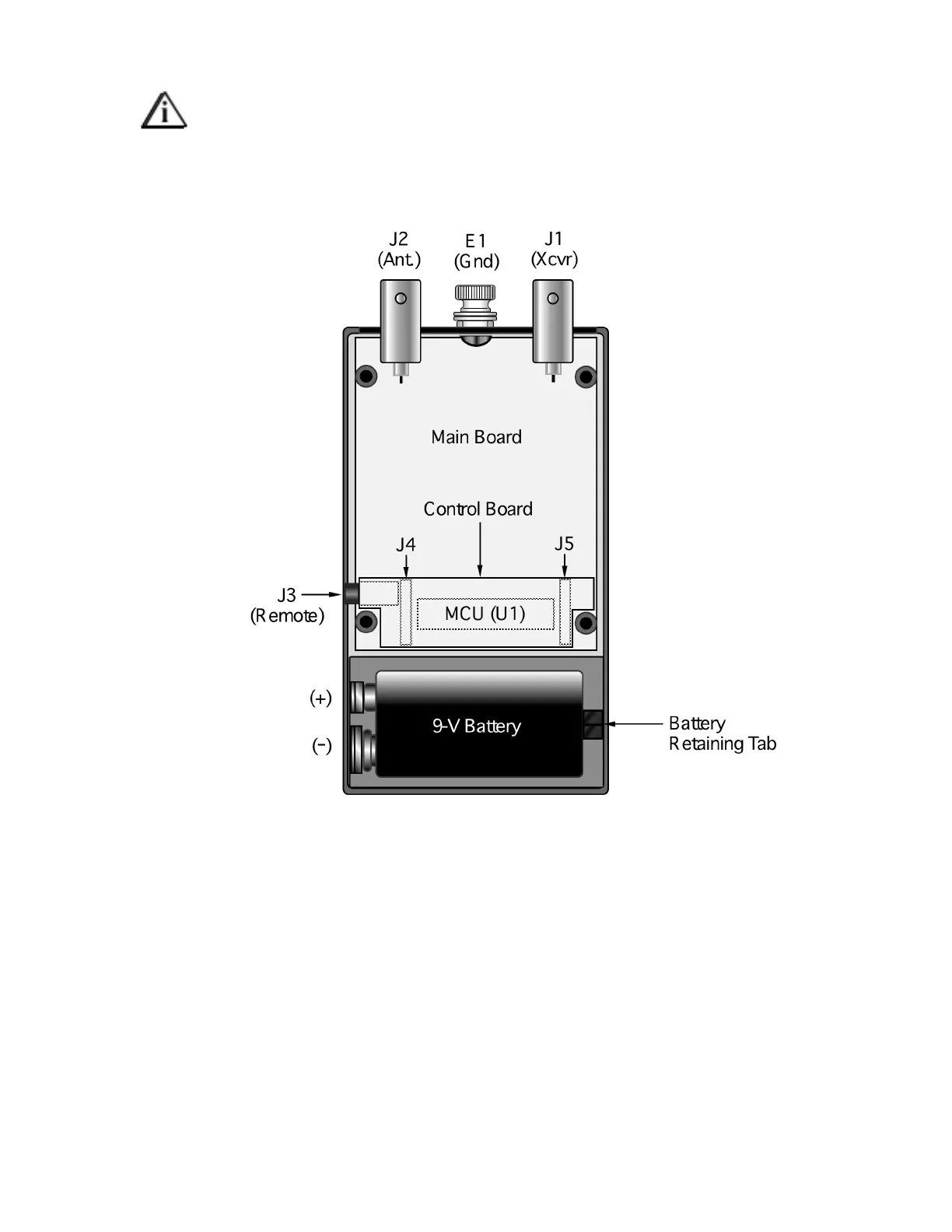
Figure 1 shows the interior of the T1. It is accessed by opening the battery compartment, then removing
four screws on the bottom of the unit. The LEDs and switches are on the Control board, which plugs into
the Main board at J4 and J5. U1, the microcontroller (MCU), is located beneath the Control board.
Figure 1