www.elecro.co.uk
5
www.elecro.co.uk
Control Circuit
The Flow-line heater is supplied with all the necessary connections to
correctly wire the control circuit that then requires nal connection to
A1 / A2 of the external contactor(s) as per the wiring diagram at rear
of this book.
Contactors are not provided with your Flow-Line heater and are
essential! Supply and tting is the responsibility of the installation
technician. These must be sited in an external cabinet and wired in
accordance with local regulations.
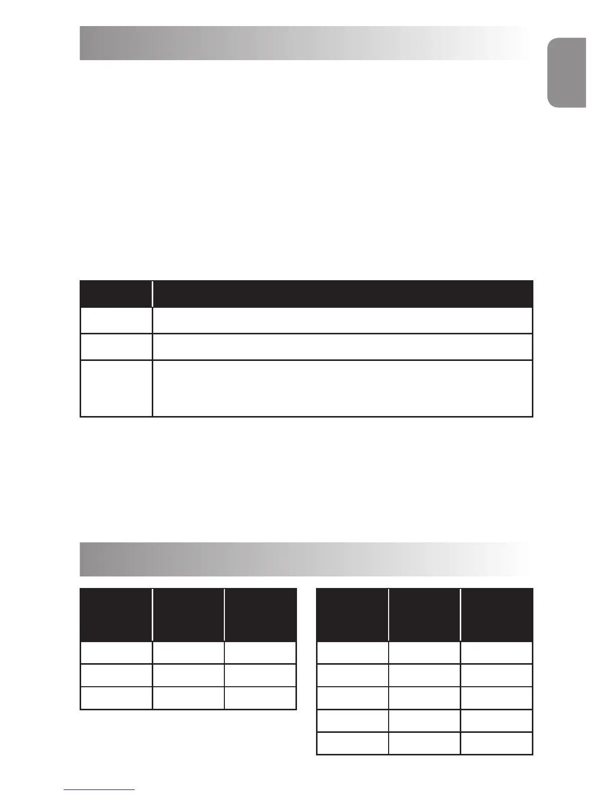
Control Components Include:
Control Circuit Important Electrical Data:
Limited by the ow switch (reed switch)
Contact Rating - 90.0 W/VA
Switching Current MAX - 1.0 Amp
Switching Voltage MAX - 230V AC
ENGLISH
Qty Description
1 0˚C to 40˚C Control Thermostat
1 55˚C Thermal cut-out (manual re-set)
1
Flow Switch Pre-Set 1,000-litres / hour for 3 ~ 6 kW (220 UK
gallons/hour)
4,000-litres / hour for 9 ~ 18 kW (880 UK gallons/hour)
Power Requirements
Power
Output
Single
Phase
Voltage
Amp
3 - kW 230V 13
6 - kW 230V 27
9 - kW 230V 40
Power
Output
3 Phase
Voltage
Amp
6 - kW 400 / 230V 9 / 15
9 - kW 400 / 230V 13 / 23
12 - kW 400 / 230V 18 / 30
15 - kW 400 / 230V 22 / 38
18 - kW 400 / 230V 26 / 46