Do you have a question about the Electro-Automatik PS 3000 C Series and is the answer not in the manual?
Details document purpose, retention, copyright, validity, and symbols.
Covers EA Elektro-Automatik's guarantee for functional competence and warranty period.
Outlines exclusions of liability for losses due to specific usage or unauthorized actions.
Instructions for proper disposal of the equipment according to European laws (WEEE).
Explanation of how to decode the product label using an example.
Specifies the intended use as power supply, battery charger, or electronic load.
Covers critical safety notices, user responsibilities, operator responsibilities, user requirements, and alarm signals.
Presents approved operating conditions, general data, and control elements.
Provides detailed technical specifications for 160W models across Voltage, Current, and Power regulation.
Illustrates front and rear views of the device, labeling key components and features.
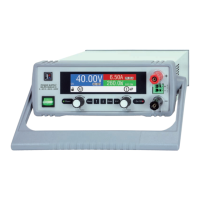
Explains the function of the color display, power LED, rotary knobs, and pushbuttons.
Introduces the PS 3000 C series as desktop units suitable for labs and educational use.
Illustrates the main internal components and their relationships, including optional interfaces.
Lists the items included in the power supply device package.
Describes available optional accessories like USB, USB/LAN, and USB/Analog interface cards.
Details the HMI display layout, actual/set value areas, and regulation modes.
Explains the function of the USB port for communication, firmware updates, and remote control.
Describes the Ethernet port for remote control and monitoring over longer distances.
Details the analog interface for remote control via analog and digital signals.
Explains the Sense input for compensating voltage drops along DC cables.
Provides recommendations for packaging and storing the device to prevent damage and corrosion.
Guides the user on how to unpack and visually inspect the equipment for damage and completeness.
Covers safety procedures before installation, preparation, and device installation.
Provides instructions for selecting the location, ensuring ventilation space, and handling the device.
Details connecting the DC output to loads, including terminal ratings and cable considerations.
Guides on connecting remote sensing for voltage compensation and cable requirements.
Instructions for connecting the optional analog interface card and D-Sub connector.
Explains how to connect the USB port for device communication and driver installation.
Outlines procedures for the first start-up, including cable checks and settings configuration.
Emphasizes operating the device only by trained personnel and safety measures for dangerous voltages.
Introduces different operating modes (CV, CC, CP) and general notes on operation.
Explains Constant Current (CC) mode, including automatic switching and voltage overshoots.
Describes Constant Power (CP) mode and the auto-range principle for power limitation.
Provides an overview of device alarms, their signaling, and acknowledgement.
Guides on powering the device, switching it off, and navigating the configuration menu.
Lists submenus within "Settings" for output, protection, limit, and general settings.
Details general settings like remote control allowance and DC output behavior after power/alarms.
Covers configuration of optional digital interfaces (USB, Ethernet) and default network settings.
Explains HMI setup options including language, backlight, status page, and key/alarm sounds.
Details how to set and use adjustment limits for voltage, current, and power values.
Guides on adjusting set values using rotary knobs and how limits affect adjustments.
Explains how to switch between different main screen layouts for displaying values.
Describes how to manually and remotely switch the DC output on and off.
Introduces remote control possibilities via analog or digital interfaces.
Explains the analog interface's capabilities for remote control and status monitoring.
Provides a detailed pinout, description, and electrical specifications for the analog interface.
Provides examples of switching the DC output using the REM-SB pin.
Explains device alarm and event handling, including acknowledgement and configuration.
Explains how to lock the control panel to prevent accidental value changes and PIN lock options.
Guides on saving and loading user profiles for settings and set values.
Discusses series connection, parallel operation, and using the supply as a battery charger.
Advises on device maintenance, focusing on cleaning internal fans and component cooling.
Covers fault finding, diagnosis, repair, fuse replacement, and firmware updates.
Outlines the procedure for returning equipment for repairs to the manufacturer.
Lists contact information including headquarter, e-mails, and telephone numbers for support.
| Current Resolution | 1 mA |
|---|---|
| Storage Temperature | -20 °C to +70 °C |
| Output Voltage | 0 V to 30 V DC (depending on model) |
| Output Current | 0-10 A |
| Power Rating | 300 W |
| Line Regulation | ≤0.01% + 2 mV |
| Operating Temperature | 0 °C to +50 °C |
| Protections | Overvoltage, Overcurrent, Overtemperature |
| Ripple Voltage | < 1 mVrms |