Do you have a question about the Electro Industries Shark 100 and is the answer not in the manual?
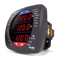
Describes the Shark 100 meter's hardware features and capabilities.
Provides detailed technical specifications of the meter.
Details the meter's accuracy specifications and performance.
Provides step-by-step instructions for ANSI panel mounting.
Provides step-by-step instructions for DIN rail mounting.
Safety and general considerations for electrical installation procedures.
Describes wiring CT leads to the meter using current gills.
Describes wiring CT leads by passing them through the meter.
Details connections for voltage and power supply inputs.
Provides various electrical wiring diagrams for different configurations.
Details on configuring the meter's profile settings via software.
Details the main configuration process and modes.
Setting up Current Transformer (CT) parameters.
Setting up Potential Transformer (PT) parameters.
Configuring the electrical connection type (Wye, Delta).
Setting communication port parameters (Address, Baud, Protocol).
The detailed Modbus register map for the Shark 100.
| Input Voltage | 120/240 VAC |
|---|---|
| Current Inputs | 5A or 1A |
| Display | LCD |
| Frequency Range | 45-65 Hz |
| Humidity | 0-95% non-condensing |
| Mounting | Panel mount |
| Measurement Type | Power, Energy, Demand |
| Communication Protocols | Modbus, DNP3 |
| Power Supply | 85-265 VAC |
| Accuracy | 0.2% |
| Operating Temperature | -20°C to 60°C |
| Storage Temperature | -40°C to 85°C |
| Dimensions | 96 x 96 mm |