Pulser Disc:
The end of the shaft to be monitored must be center drilled to a
depth of 1/2–inch with a #21 drill and tapped for a 10-32 UNF.
After applying Loctite™ or a similar adhesive on the threads
to keep the pulser disc tight, the pulser disc should be attached,
decal side out with the supplied 10-32UNF machine screw and
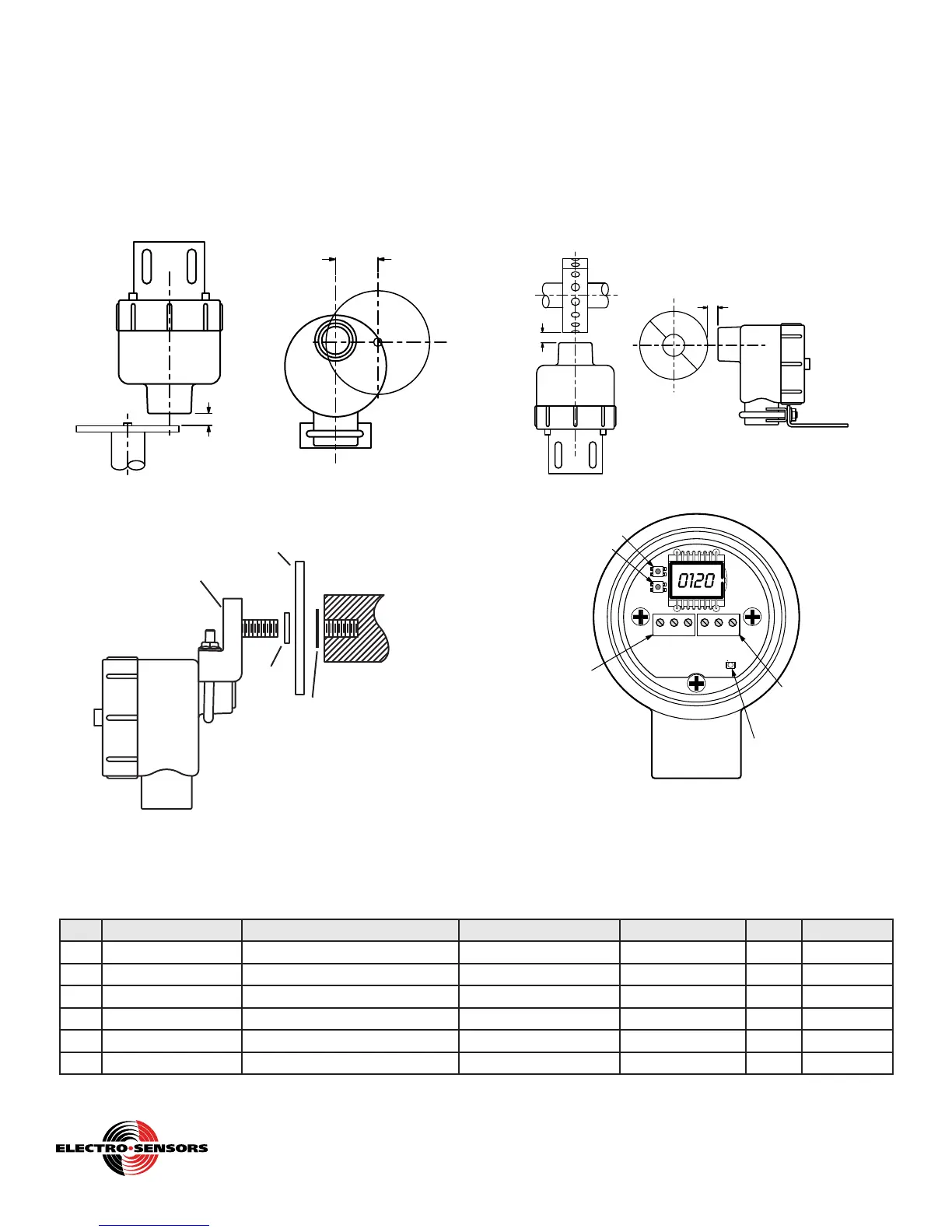
lock washer. Dimension (A )is 1/16 inch to 1/4 inch.
The center-line of the magnets (B) must align with the center of
the sensing head as the Pulser Disc rotates.
A
B
Figure 4a: FB420 with 255 Pulser Disc
EZ-Mount Bracket with Pulser Disc (Optional)
Shaft Center Drilled
and Tapped for
1/2-13 UNC 2A
Retaining
Washer
(Included)
Spacer
(Included)
Pulser Disc (Included)
EZ-Bracket
Assembly
FB420
Figure 4b: FB420 with EZ-Mount Bracket
Pulser Wrap (optional):
Pulserwrapsarecustommanufacturedtottheshafttheywill
be mounted on. When the wrap is shipped, four Allen-head cap
screws hold the two halves of the wrap together. These screws
must be removed so the wrap is in two halves. Place the halves
around the shaft, reinsert the screws and torque them to 8 foot-
pounds. Dimension (A) is 1/16 inch to 1/4 inch.
The center-line of the magnets (B) must align with the center of
the sensing head as the Pulser Wrap rotates.
A
A
B
Figure 4c: FB420 with Pulser Wrap
D5
SW2
SW1
321
TB2
321
TB1
SW1: Increment Button
SW2: Enter Button
Relay LED
TB1-1: +24Vdc Pwr
TB1-2: 4-20mA Out
TB1-3: DC Ground
TB2-1: N.O.
TB2-2: Common
TB2-3: N.C.
Figure 5: FB420 Rear-View (Cover Removed). Showing the
power/signal terminal TB1, the relay terminal TB2, the push-
buttons SW1 and SW2, and the relay LED
2-4
Free Catalog and Application Assistance
1.800.328.6170
Website: www.electro-sensors.com
990-003400 Revision C
List of Variables
VA R Mnemonic Description Range Decimal Place Default User’s Value
01 Pulses Per Rev Pulses per revolution of target 0001. to 9999. Fixed at XXXX. 0008
02 Min. RPM RPM value corresponding to 4 mA 0000 to “97.5% of Var03” dec pt tied to Var03 0000
03 Max. RPM RPM value corresponding to 20mA 0.000 to 9999. User selectable 200
04 Relay Function Select Unused, Over-speed, Under-speed 0000. to 0002. Fixed at XXXX. 0000
05 Relay Set-point RPM Relay alarm trip point in RPM 0000 to 9999 dec pt tied to Var03 0000
06 Relay Set-point Delay Alarm event ‘wait’ time in seconds 0000. to 0030. Fixed at XXXX. 0000
 Loading...