Dx34A Digital Sound System Processor
Dx34A Digital Sound System Processor
Specifications
Conditions:
1.0 dBu = 0.775 volts rms.
Overall Specifications
Input/Output Configuration:
Two in/four out; stereo two way,
dual mono two way, mono three
way with a fourth full-range direct
out (low and direct outs may be
the sum of two input channels) or
mono four way
Crossovers,
Characteristics:
Butterworth, Bessel and
Linkwitz-Riley
Slopes:
6, 12, 18 and 24 dB per octave
Equalizers,
Low Shelving,
Number:
Two
Corner Frequencies:
Variable from 20 to 500 Hz
Slopes:
6 or 12 dB per octave
Gain:
0 to ±12 dB in 1-dB steps
Parametric,
Number:
Eight
Center Frequencies,
Low and Low-Mid Outputs:
Variable from 20 Hz to
5,000 Hz
Mid Output:
Variable from 30 Hz to
12,500 Hz
Mid-High Output:
Variable from 50 Hz to
20,000 Hz
High Output:
Variable from 500 Hz to
20,000 Hz
Input (two-way configuration
only):
Variable from 20 Hz to
20,000 Hz
Q:
Variable from 0.4 to 20
Gain:
0 to ±12 dB in 1-dB steps
High Shelving,
Number:
Two
Corner Frequencies:
Variable from 500 Hz to 16,000 Hz
Slopes:
6 or 12 dB per octave
Gain,
6-dB-per-octave slope:
0 to ±12 dB in 1-dB steps
12-dB-per-octave slope:
0 to +6/-12 dB in 1-dB steps
Low Cut,
Number:
Two
Corner Frequencies:
Variable from 20 Hz to 200 Hz
Slopes:
6 or 12 dB per octave
Q (12-dB-per-octave slopes only):
Variable in eight steps from 0.5 to
2.0 (Q = 2.0 suitable for B
6
alignment of vented low-fre-
quency systems)
Frequency Resolution of Variable
Cross-over and Corner Frequencies
(see above),
20-50 Hz:
1 Hz
50-100 Hz:
2 Hz
100-200 Hz:
4 Hz
200-500 Hz:
10 Hz
500-1,000 Hz:
20 Hz
1,000-2,000 Hz:
40 Hz
2,000-5,000 Hz:
100 Hz
5,000-10,000 Hz:
200 Hz
Lock-Out Provision:
Disable and enable access to
internal functions of unit
Frequency Response:
20-20,000 Hz ±0.3 dB
Total Harmonic Distortion, 1,000 Hz,
without Transformers:
<0.01%
with Transformers:
<0.1%
Signal-to-Noise Ratio, Typical:
>102 dB
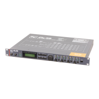
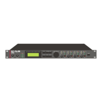
Front-Panel Controls (see Figure 2):
Input gain control; output level
controls (analog) (four); endless
rotary encoder/push-to-enter button;
edit/two-way button; <select/three-
way button; select>/four-way button;
store button; option button; mute
button; power on/off switch
Front-Panel Displays (see Figure 2):
8-segment LED input level indica-
tors (two), including clip, with peak-
hold or slow-mode ballistics; 6-
segment LED output level indicators
(four), including clip, with peak-hold
or slow-mode ballistics; output
limiter status indicators (four); 2 x
16-digit back-lit alphanumeric
display; edit mode LED; lock mode
LED; channel(s) muted LED
Limiters:
Four digital limiters with threshold
variable over a 21-dB range and
variable attack and decay times
Signal Delays,
Master:
2 to 1,000 msec
Output (four):
0 to 20 msec
Increment:
21 µsec
Data Format:
18-bit linear, 24-bit internal
A/D Conversion:
18-bit linear sigma-delta, 64-times
oversampling, linear phase
D/A Conversion:
18-bit linear, eight-times
oversampling, linear phase
Sampling Rate:
46.875 kHz
MIDI Configuration,
Functions:
Data dump;
Master/slave operation
Connectors, In and Out (see Figure 2):
5-pin DIN (180° pin pattern)
Common-Mode Rejection Ratio
(CMRR), 1,000 Hz:
>70 dB
Grounding:
Ground-lift switch disconnects
ground from chassis to eliminate
hum
Chassis Construction:
Painted steel
 Loading...