Do you have a question about the Electro-Voice Xi-1153/64 and is the answer not in the manual?
Introduces the X-Array Install™ series and RMD™ technology.
Lists key technical features like RMD™, line array configuration, and specific drivers.
Discusses suitable environments and system pairings.
Explains power handling capabilities and relevant testing standards.
Details specific parameters used for power testing.
Discusses system controllers and configuration options for optimal performance.
Explains connector types and pin assignments for system wiring.
Provides guidance on suitable amplifiers for optimal system performance.
Details the flying system, hardware, and safety precautions.
Lists available replacement parts and their corresponding part numbers.
Provides detailed technical specifications for system design and integration.
Outlines warranty terms, conditions, exclusions, and service procedures.
Explains the measurement process for polar response data.
Presents directional response data across various frequencies.
Presents the system's frequency response graph.
Explains and presents beamwidth data at -6dB points.
Explains and presents directivity index (D) and factor (R).
Explains and presents harmonic distortion data.
Presents the impedance graph for different frequency bands.
Illustrates the wiring diagram for each frequency band.
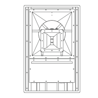
Shows the physical dimensions of the loudspeaker system.
Lists specific frequency response, efficiency, and power handling figures.
Summarizes key performance metrics: beamwidth, directivity, distortion, and impedance.
Details the drivers used and input connection types.
Recommends amplifier power and describes enclosure construction.
Lists overall dimensions, weight, and rigging details.
| Operating Mode | Passive |
|---|---|
| Nominal Impedance | 8 Ohms |
| Type | Full-range |
| LF Driver | 15 in |
| Input Connections | 2x Neutrik NL4 |
| Enclosure Material | Plywood |