EasyManua.ls Logo

Electrolab RediLevel 2100 DLS - User Manual

Electrolab RediLevel 2100 DLS
29 pages
Print Icon
To Next Page IconTo Next Page
Loading...
EL 29306 © 2022 Electrolab, Inc. All Rights Reserved.
USER MANUAL
MODEL 2100 DLS PRODUCT LINE
REDILEVEL 2100 DLS

Table of Contents

Question and Answer IconNeed help?

Do you have a question about the Electrolab RediLevel 2100 DLS and is the answer not in the manual?

Overview

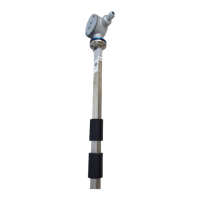
The RediLevel™ 2100 DLS is a digital level sensor designed to measure and report fluid levels and temperatures in various tanks and vessels. Its thin-profile, sturdy design allows it to fit into tanks with two-inch ports. The sensor uses one or two floats embedded with magnets to detect the top fluid level(s). A two-float sensor can measure multiple fluids in a tank. A temperature sensor is mounted inside the tube, fourteen inches from the bottom. When polled, microprocessors determine the float position(s), calculate the level and temperature, and transmit the data in a serial stream.

Technical Specifications:

  • Measurement: Fluid levels and temperatures.
  • Design: Thin-profile, sturdy, fits into 2-inch NPT female tank ports (2.1995-inch opening).
  • Float Type: Polyamide float carrier with nitrophyl.
    • One float for single liquid measurement.
    • Two floats for multi-fluid measurement.
  • Level Measurement:
    • Increments: 1/4 inch resolution.
    • Accuracy: +/- 1/8 inch.
  • Temperature Measurement:
    • First temperature sensor: 12-14 inches from the bottom.
    • Standard: One temperature sensor.
    • Optional: Up to 8 temperature sensors with desired spacing.
    • Accuracy: +/- 1.5° C.
    • Operating Temperature Range: -40° C to 80° C.
  • Power Requirements: 5.6 VDC to 13 VDC.
  • Power Consumption: 15mA nominal, 20mA maximum.
  • Pressure:
    • Standard: 40 psi.
    • Optional: 250 psi.
  • Communication:
    • Type: RS485.
    • Wiring: Two-wire or four-wire communications, field selectable via jumpers on the fuse board.
      • Two-wire: Two twisted pair (16-18 AWG) recommended.
      • Four-wire: Three twisted pair (16-18 AWG) recommended.
    • Baud Rate: Programmable (up to 57600 baud, v.3.15 and higher). Default is 9600, N, 8, 1.
    • 4-20mA Signal: Available when connected to a digital-to-analog converter board.
    • Wireless: Capable.
  • Protocol:
    • Modbus RTU 16 bit unsigned integer (v3.13 and higher).
    • Modbus RTU 32 bit floating point (v3.13 and higher).
    • Modbus RTU (2x 16 bit) for alternate 32 bit floating point (v3.14 and higher).
    • Serial data via ASCII.
  • Classification: Class I, Div. 1, Group D Hazardous Locations (when connected to an approved intrinsically safe barrier board).
  • Certification: ANSI/UL-913, CAN/CSA C22.2, No. 157.
  • Tubing Material: 18 gauge, 316L stainless steel.
  • Dimensions: 0.75" x 1.5".
  • Measurement Length: 2 to 12 ft.
  • Total Tube Length: Default is Measurement Length plus 18 inches. For dome-top tanks, order 1' longer than tank height.

Usage Features:

  • Digital Output: Reports information in a serial bit stream.
  • Multi-Fluid Measurement: Two-float sensors can measure multiple fluids.
  • Configurable Baud Rate and Parity: Allows customization for different communication setups.
  • 4-20mA Output: Provides an analog output signal when connected to a converter board.
  • Modbus Compatibility: Supports various Modbus RTU modes (16-bit unsigned integer, 32-bit floating point, 2x16-bit floating point) for integration with SCADA or RTU systems.
  • ESD Mode: Features a High Level Electronic Shut Down (ESD) mode to prevent cycling power, responding with maximum level for a programmed number of polls.
  • Unit Number Assignment: Sensors can be pre-addressed with specific unit numbers for multi-sensor installations.
  • Level Error Setting: Configurable error reporting (999.99 or 000.00).
  • K Factor: Adjustable K factor for volume calculations (10 to 1000 bbls/in).
  • Poll Period: Configurable 4-20mA poll period (default 30 seconds). Note that periods less than 20 seconds may shorten the life of the 4/20mA converter board.
  • Receive to Transmit Delay: Adjustable delay (50 to 250 milliseconds, default 127ms).

Maintenance Features:

  • Sensor Calibration Procedure (Setting the Initial Offset):
    • The only required calibration is setting the offset value.
    • This can be done in the sensor or at the EFM, RTU, or PLC.
    • Requires comparing the electronic reading with an actual gauged level in the tank.
    • The tank should ideally not be in active production to avoid fluid agitation during calibration.
    • If no fluid is in the tank, the level offset cannot be determined.
    • The offset value is always added to the raw value. Resetting to zero is recommended if a mistake is made.
    • Procedure involves using a Hand-Held Communicator (HHC-1000) to take initial readings, verify float separation (if two floats are used), ensure the first level is above 3 inches, measure actual level with a gauge line, calculate the offset, and program it into the sensor.
  • Troubleshooting Guide:
    • Sensor does not respond: Check sensor wiring, baud rate (default 9600, N, 8, 1), and power supply (5.6 to 13 VDC).
    • Sensor has been in service but not working: Check wiring connections, damaged cables, blown fuses or shorted suppressor on the barrier board, and potential damage to sensor electronics.
    • Sensor sends inaccurate level or temperature: Check for incorrect level or temperature offset programming, incorrect number of floats, and reprogram the sensor if needed.
    • Sensor sends temperature but no valid level: Check for error code 1 (float not on sensor or incorrect orientation), and verify the number of floats programmed.
  • Health Status Report: Provides information on sensor operation parameters, including error and warning messages (e.g., NO-SWITCH-CLOSED, ONLY-ONE-GROUP-FOUND-ON-A-TWO-FLOAT-SYSTEM, LOW-BATTERY).
  • Battery Voltage Report: Allows checking the battery voltage.
  • Serial Number and Version Number Reports: Useful for identification and tracking.

Electrolab RediLevel 2100 DLS Specifications

General IconGeneral
BrandElectrolab
ModelRediLevel 2100 DLS
CategoryAccessories
LanguageEnglish