27
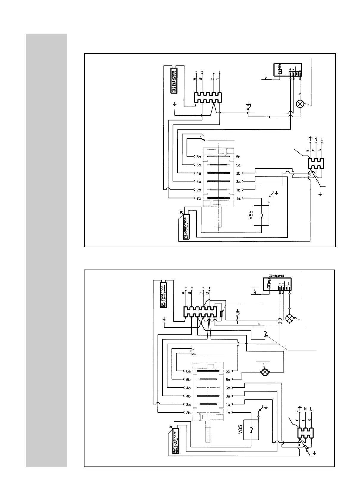
3. Wiring diagram with automatic ignition and no interior light
4. Wiring diagram with automatic ignition and interior light
spark plug
light DC --
re
e
d
c
o
n
ta
c
ts
(s
e
n
s
o
r s
w
itc
h
in
g
)
* resistor (replaced by a bridge for 24V battery voltage)
ignition control lamp
thermo cut-off current
mains connection ~
to casing
heating-
element
AC~
ground
battery connection
12V/24V --
mains connection ~
to casing
thermo cut-off current
heating-elem
ent D
C
-
reigniter
spark plug
to casing
to casing
heating-
element
AC~
from battery
heating-element DC -
Battery connection 12V/24V -
A = Ground heating element DC, white
B = Heating element DC-, red
C = Ground automatic ignition, black
D = Automatic ignition violet
ground
ignition control lamp
to casing
battery connection
12V/24V --
* resistor
to casing
Battery connection 12V/24V -
A = Ground heating element DC, white
B = Heating element DC-, red
C = Ground, automatic ignition black
and interior light,
D = Automatic ignition and violet
interior light
from battery